
The Impact of Routing
This topic explains how to check the impact of the characteristics and routing of decoupling capacitors.
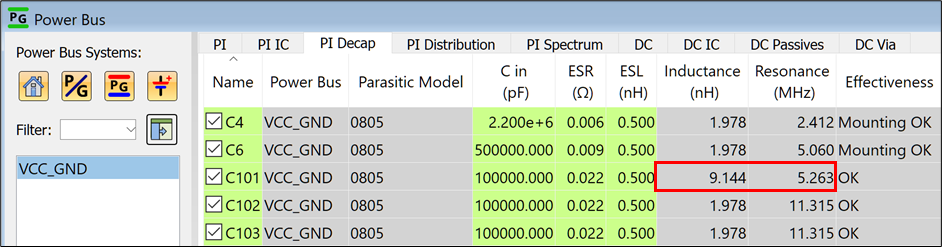
- In the PI/EMI Analysis module, select the Power Bus view, PI Decap tab. For each decoupling capacitor, the following values are displayed in this tab: capacitance, inductance, resistance frequency, connected bus power name (supply source), nearest IC, etc.
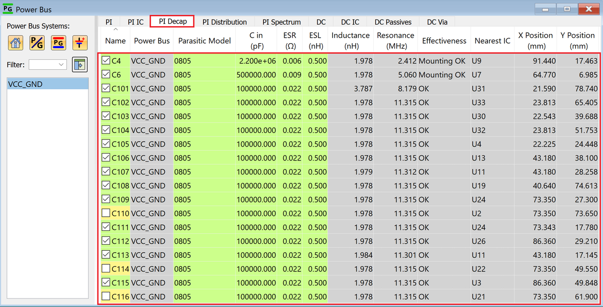
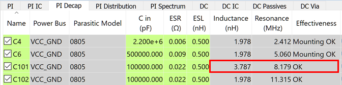
- Check the inductance and resistance frequency of C101.
- Inductance is the total inductance element that is associated with the bypass loop, from the decoupling capacitor to a powerplane.
- Resistance frequency is a self-resonant frequency in the characteristics of the decoupling capacitor, in consideration of the tracks around it.
- In the PI/EMI Analysis module, click File > Quit.
- If requested, click Save to save the data.
- On the eCADSTAR PCB Editor ribbon, select View > Lowlight to hide the lowlight view.
- On the Status Bar, set Active Layer to "Conductor-1" , and deselect the Select Only Active Layer check box.

- Click a clear area on the canvas, to ensure that no items are selected.
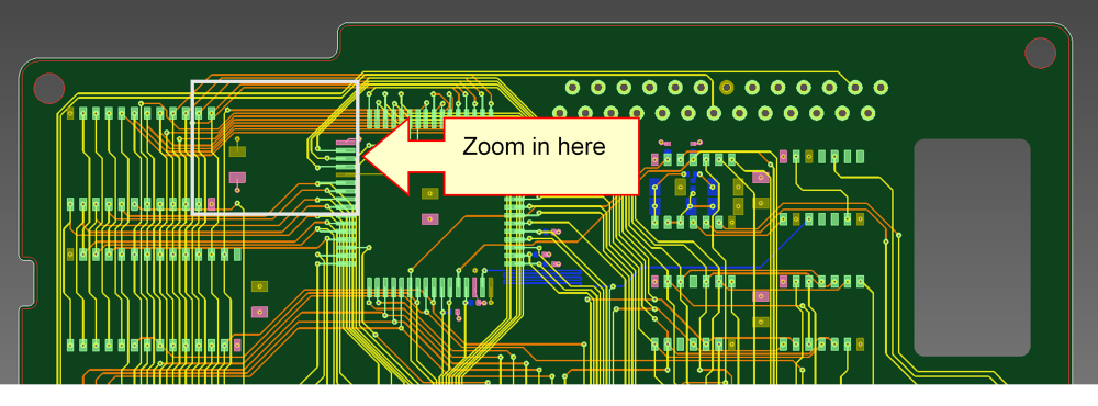
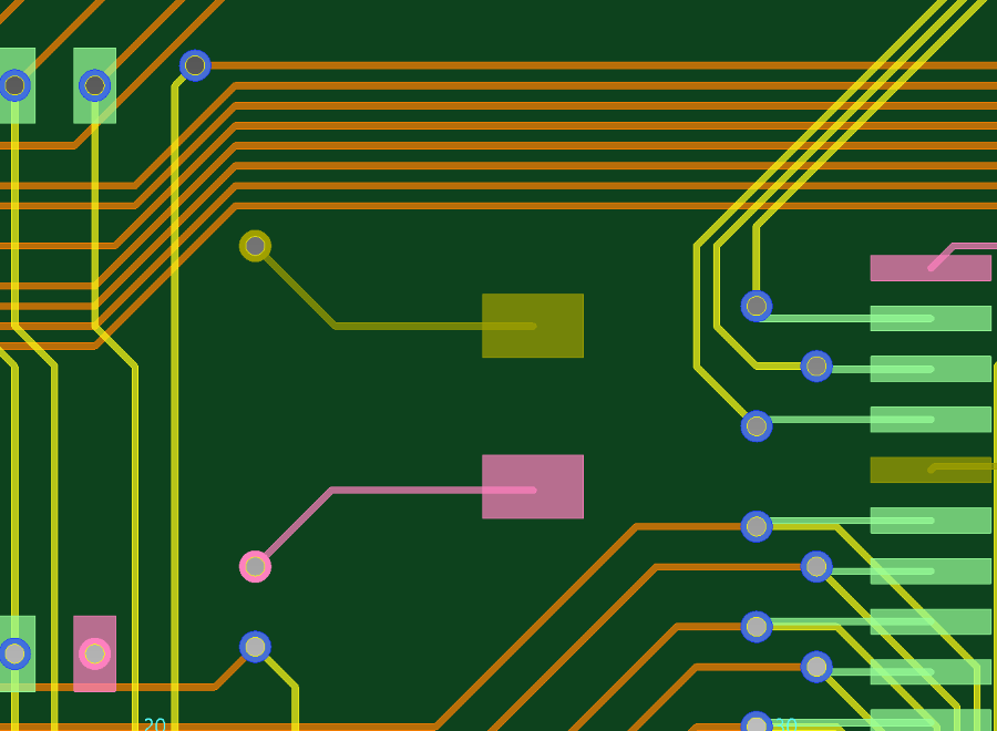
- To change the placement and routing of the decoupling capacitor, zoom in to an area that encloses C101. (the square box in the figure).
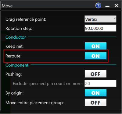
- Select Home > Move > Move on the ribbon. The Move dialog is displayed.
- In the Move dialog, ensure that Reroute is set to ON. The tracks between the component pins and vias are rerouted.
- To change the track around C101 to a longer and thinner one, select the C101 component. You may need to press Shift+Click to start moving the component.
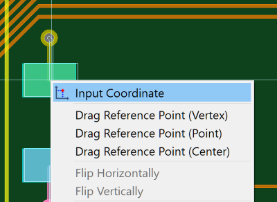
- Right-click, and select Input Coordinate on the assist menu.
- In the Input Coordinate dialog, set the Mode to Relative.
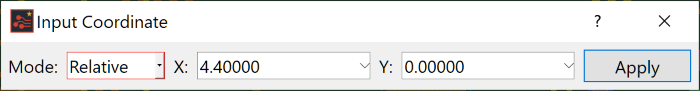
- Set X: to “4.40000” and Y: to “0.00000”, and then click Apply. The component C101 is moved to its new position, and the tracks are automatically rerouted.
- Close the Input Coordinate and Move dialogs.
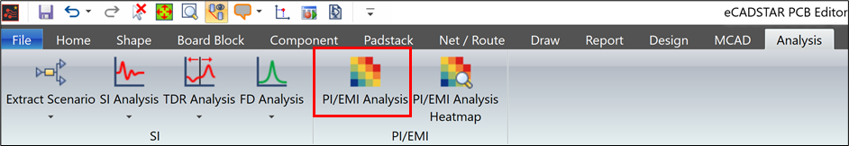
- On the ribbon, click Analysis > PI/EMI > PI/EMI Analysis, and then close the Supply Pin Type Report dialog that is displayed.
- In the PI/EMI Analysis module, ensure that VCC_GND is selected in the Power Bus view.
- On the toolbar, click
 PI Analysis.
 - Select the Power Bus view, PI Decap tab to check the inductance of C101.
Note that the value is larger. This is because the increased routing has increased the inductance. Also, with the increase of the inductance component, the self-resonant resistance frequency has shifted to a lower level. This indicates that the Inductance at a lower resonant frequency has become dominant.
This task is demonstrated in the following video.
