
The Effects of a Decoupling Capacitor
This topic explains how to check the difference of impedance, depending on whether a decoupling capacitor is present.
- In the PI/EMI Analysis Heatmap dialog, select Any and set the range to "0" - “7".
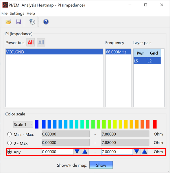
- Changing the Color scale settings changes the colors of the displayed result, as shown below.
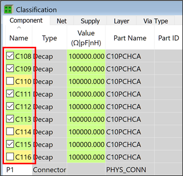
- Disable the fitted states for decoupling capacitors as follows.
- In the PI/EMI Analysis module, select the Classification view, Component tab.
- Click on the columns for C110, C114 and C116 to deselect their check boxes.
- On the toolbar, click
 PI Analysis to perform the PI analysis
again.
PI Analysis to perform the PI analysis
again.
There may be a delay in completing the PI Analysis.
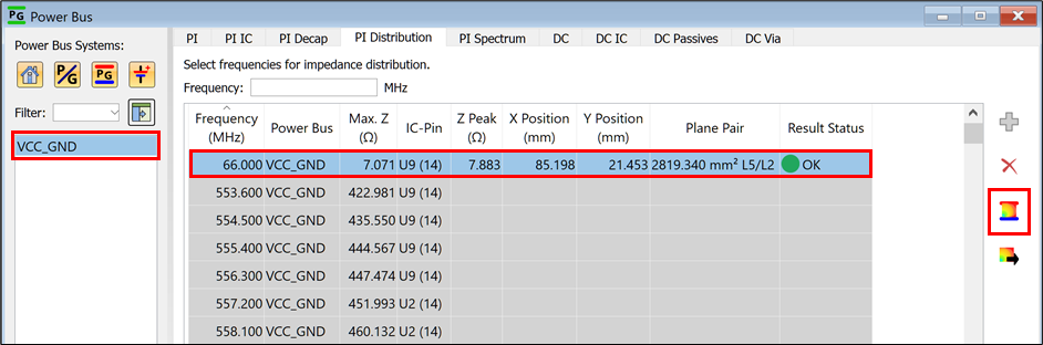
- Select the Power Bus view, PI Distribution tab.
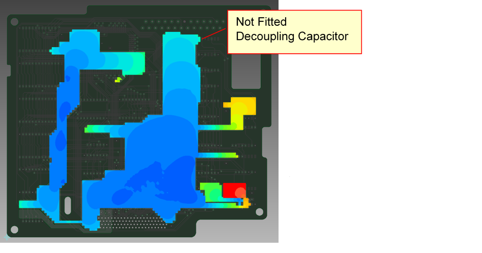
- Recreate the impedance map at 66 MHz for VCC_GND, as follows.
- Select VCC_GND in the Filter list.
- Select the row for 66.000 MHz, and click
 Generate
impedance distribution for selected frequencies.
Generate
impedance distribution for selected frequencies.
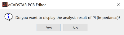
- Click Yes to display the results of the analysis.
- In the Impedance Distribution Heatmap dialog, configure the same settings that you specified in the Checking Impedance Distribution topic.
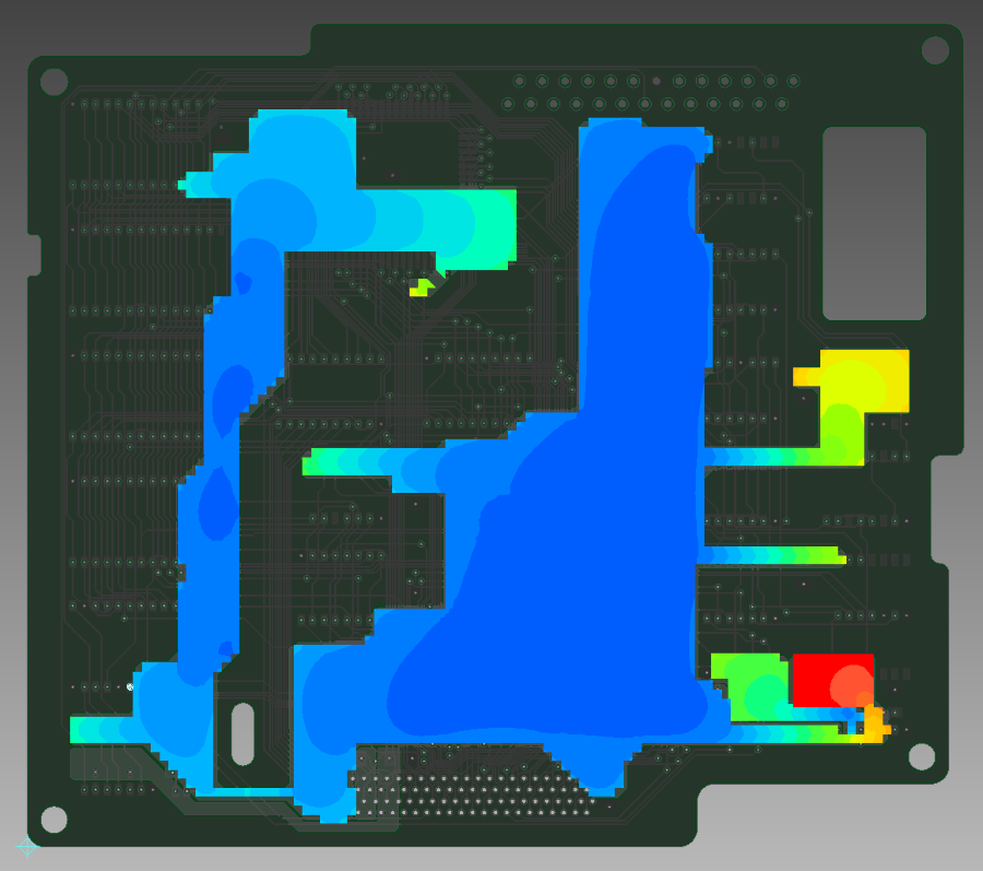
- On the canvas in eCADSTAR PCB Editor, confirm that the distribution has changed.

- Select File > Close in the PI/EMI Analysis Heatmap dialog.
This task is demonstrated in the following video.
Related Topics
Performing PI Analysis
Checking Input Impedance
Checking Impedance Distribution
