
Component Attributes
This topic describes how to check and set the component attributes related to EMI analysis.
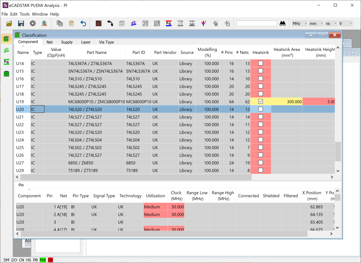
- On the menu bar in the PI/EMI Analysis Module, click Window > Cascade, and then click Window > Classification.
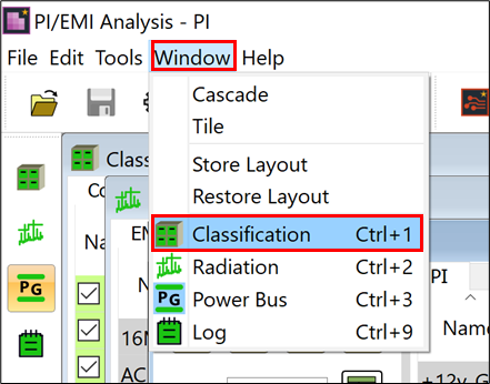
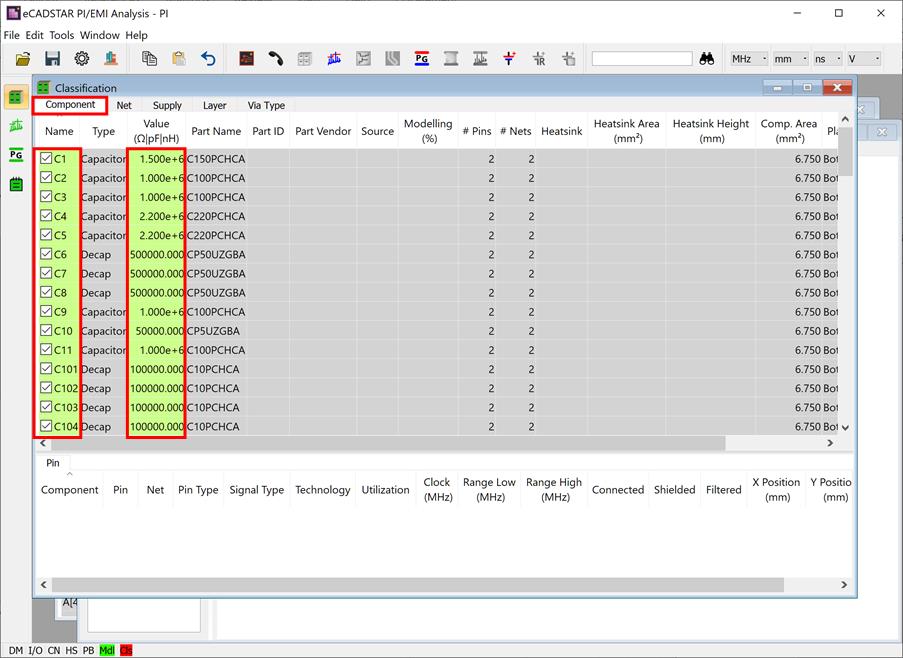
The Classification view is displayed.
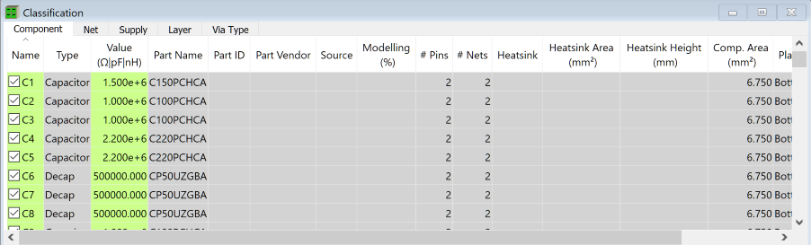
- In the Component tab of the Classification view, you can change constants, fitted flags and other attributes for analysis. In the Component tab, the Value column shows the allocated value for the component that is set in Library Editor. If the check box for the Name column is selected for the component, then it is fitted.
Note
In the Classification view, the cells where data can be entered or set are displayed in the following colors according to the reliability of the value.
In the Classification view, the cells where data can be entered or set are displayed in the following colors according to the reliability of the value.
| Value | Description |
|---|---|
|
Indicates an attribute that is automatically set by referring to design data, or the simulation library. |
|
Indicates an attribute that is handled as a default value. This is because it does not exist in the design data or simulation library. |

|
Indicates an attribute that has been changed in the PI/EMI analysis module. |
- To configure heatsink settings, select the Heatsink check box for U19 and enter "300" in the Heatsink Area column.
Note
- The Heatsink Area and Heatsink Height columns are initially populated with values.
- Heatsink Area: this is defined by the bounding box area of the footprint in the design.
- Heatsink Height:
a default value of 5.000 mm is set.
- The heatsink definition is an optional item. However, the defined data is considered when calculating common mode noise.
This task is demonstrated in the following video.
