
Assigning Models
The following procedure describes how to assign simulation models using Electrical Editor, and specify the length of a transmission line.
Simulation models must be imported into the local simulation library for each individual scenario that is created by this method. Before proceeding with assigning models in this task, ensure that the local simulation library is populated. See Task 1: Managing Simulation Models.
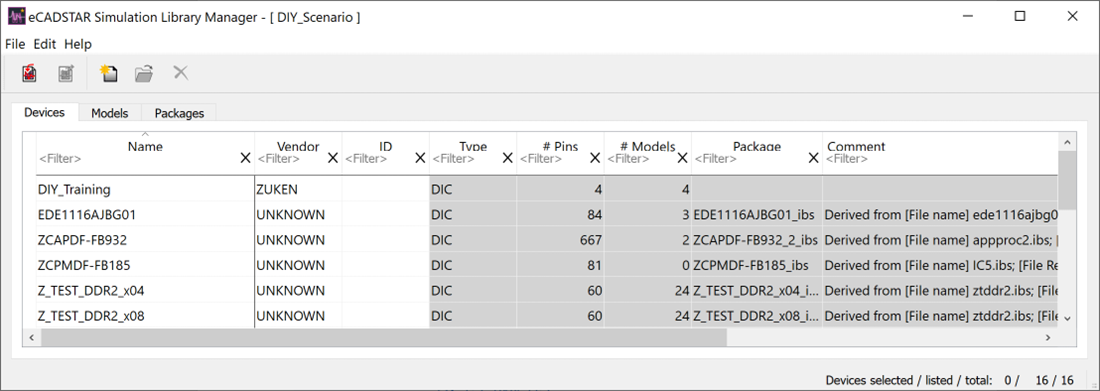
- On the Electrical Editor menu, select Tool > Manage Simulation Library to open the eCADSTAR Simulation Library Manager dialog.
- In this dialog, select File > Import on the menu to open the File Browser dialog.
- Browse to “C:\Users\Public\eCADSTAR\eCADSTAR [Version]\Analysis\Sim_Models”, and select the “SI_models.ixf” file.
- Click Open to display the eCADSTAR Simulation Library Import dialog.
- Select the four rows that contain the word "Device", and click Edit > Import on the menu. The Import Assistant dialog is displayed.
- Click Next for the devices.
- For the models, select Overwrite existing items and click Finish. The Import Assistant closes, and the devices and models are imported into the local simulation library for the scenario.
- Close the eCADSTAR Simulation Library Import dialog.
- Close the eCADSTAR Simulation Library Manager.
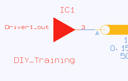
- On the Electrical Editor canvas, select the driver object and click Assign Model on the assist menu.
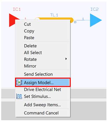
The Select Model dialog is displayed.
- In the 1: Specify how to select models section, click Select from list of available buffer models and choose "Driver1" from the list.
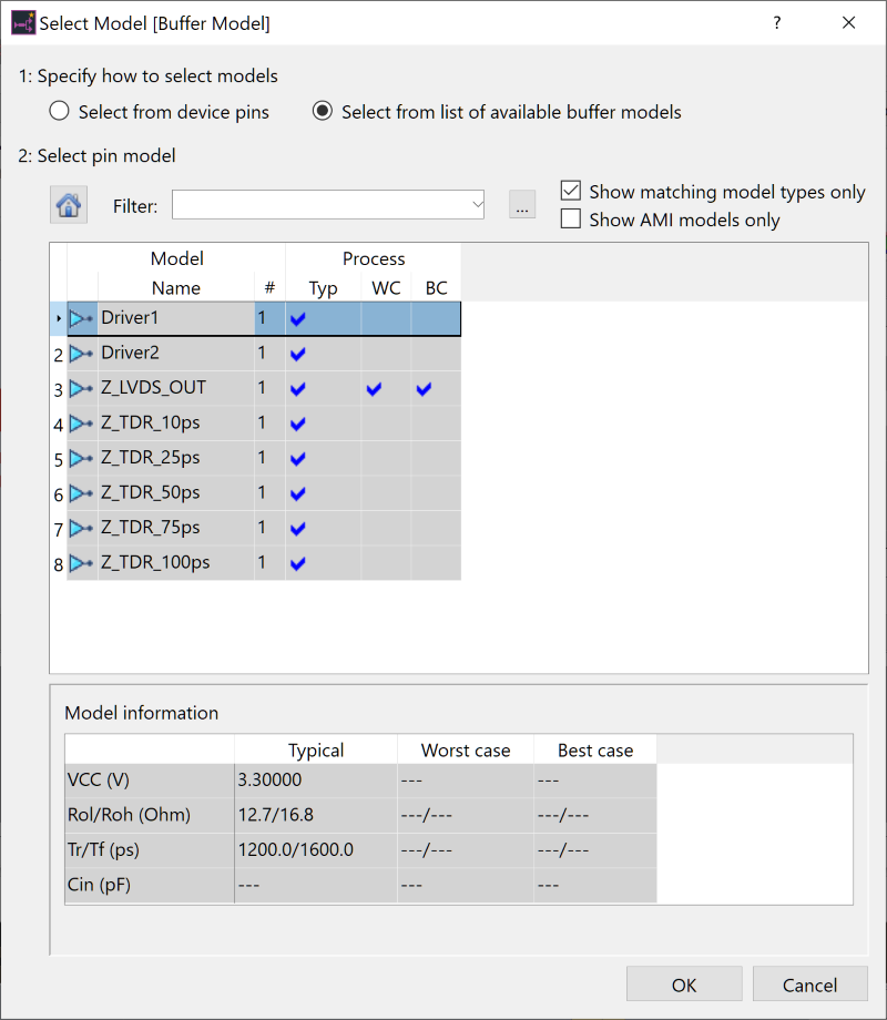
- Click OK to close the dialog and assign the model. The simulation model is assigned to the driver.
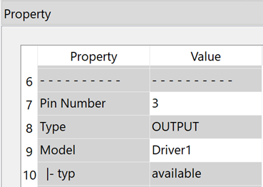
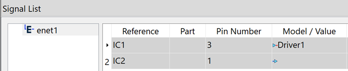
You can check assigned simulation models in the Property panel or Signal List panel.
- You can also open the Select
Model dialog from the Property
panel. You will use this method to assign the "Receiver1"
model to the receiver.
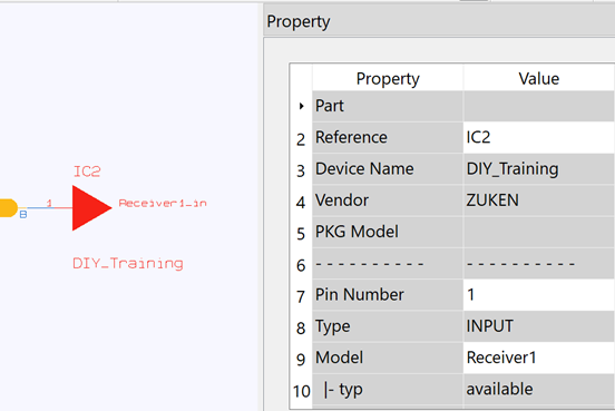
Begin by selecting the receiver object, shown in the following image.
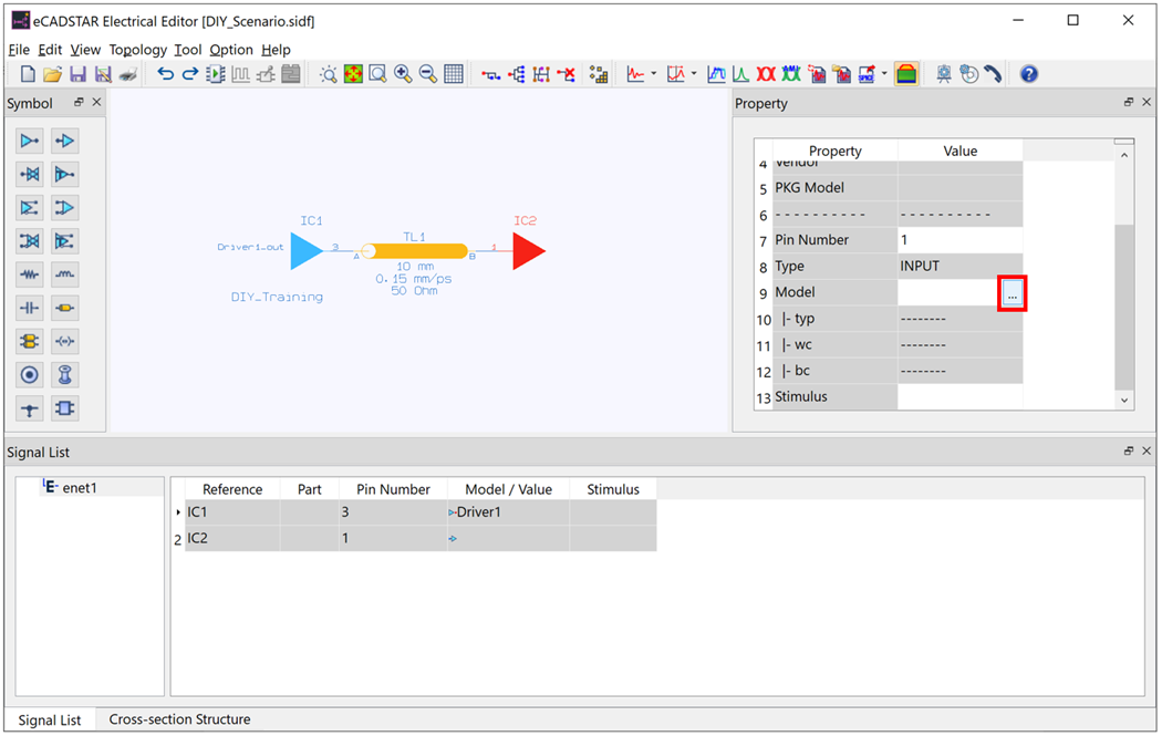
- In the Property
panel, point the cursor at the cell next to Model,
and click the displayed
 button. The Select Model dialog is
displayed.
button. The Select Model dialog is
displayed.
- In the Select Model dialog, ensure that Select from list of available buffer models is selected, and then select "Receiver1" and click OK. The simulation model is assigned to the receiver.
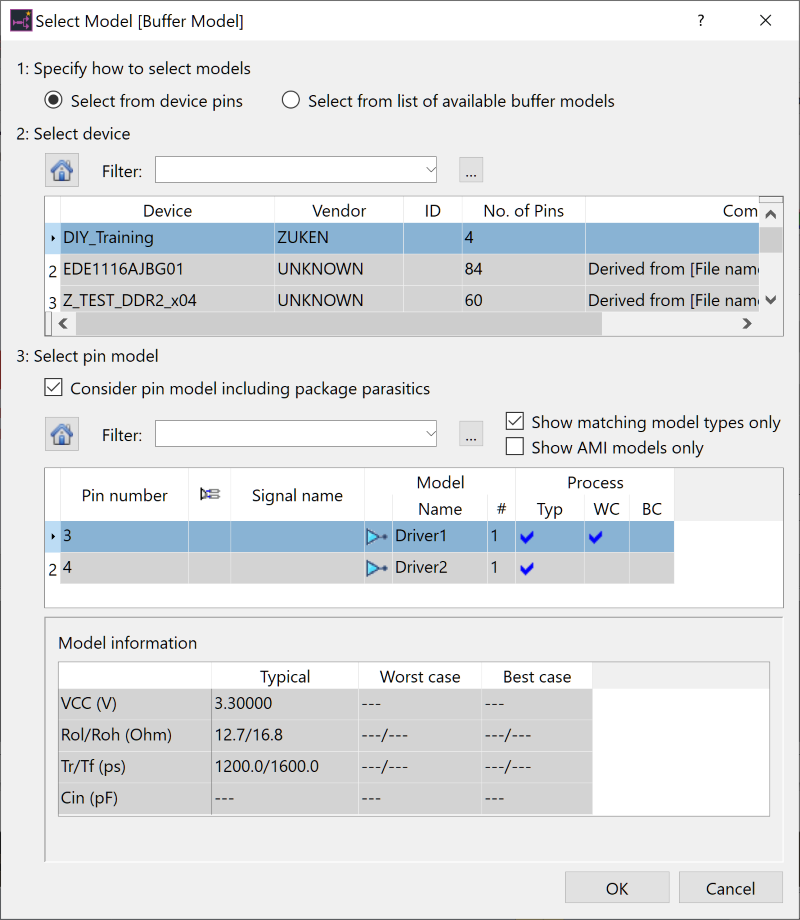
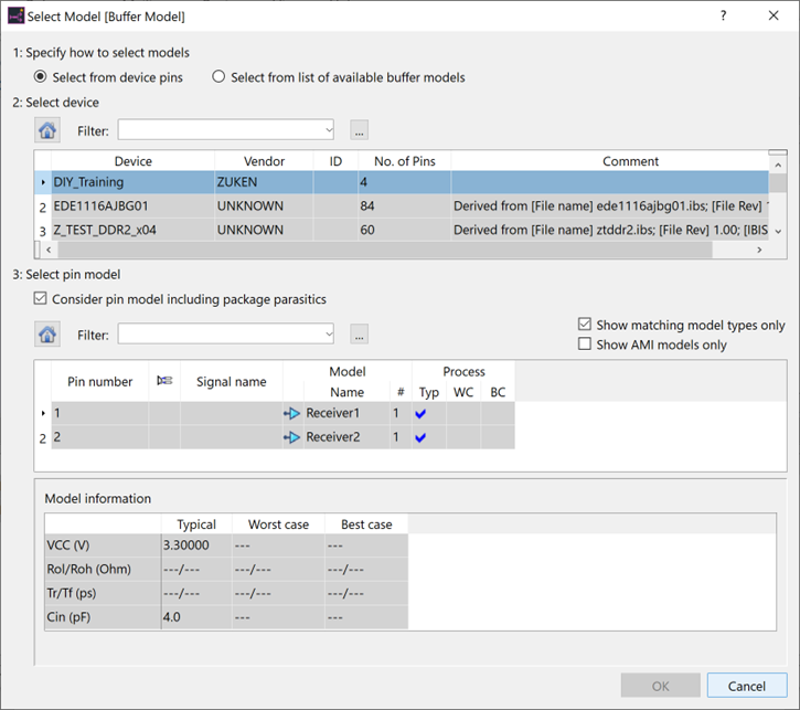
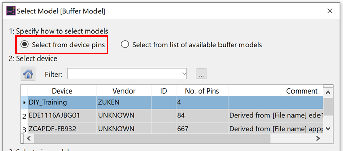
Choosing Select from device pins in the 1: Specify how to select models section allows you to assign a device-aware buffer model, including the package components contained in the device.
Specifying the Length of the Transmission Line
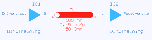
- In the Electrical Editor canvas, select the transmission line symbol.
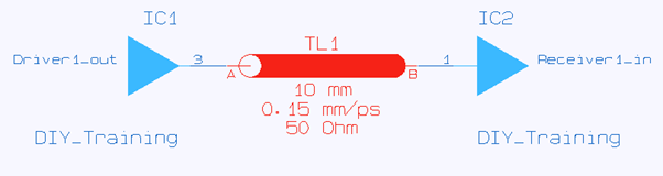
- In the Property panel, type "100" in the cell by the Length box.
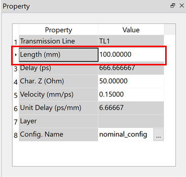
The length of the transmission line is changed.
This task is demonstrated in the following video.
