
Crosstalk Analysis
Crosstalk noise occurs between parallel tracks that are adjacent to each other. This noise is generated when a change in the signal on one track affects the other track. The noise source is referred to as the "Aggressor", and the signal in which the noise is generated is the "Victim". By setting the input waveform of the Victim signal to a constant voltage on the Low side, you can check the impact caused by the Aggressor.
- On the Electrical Editor menu bar, click File > New. The New dialog is displayed.
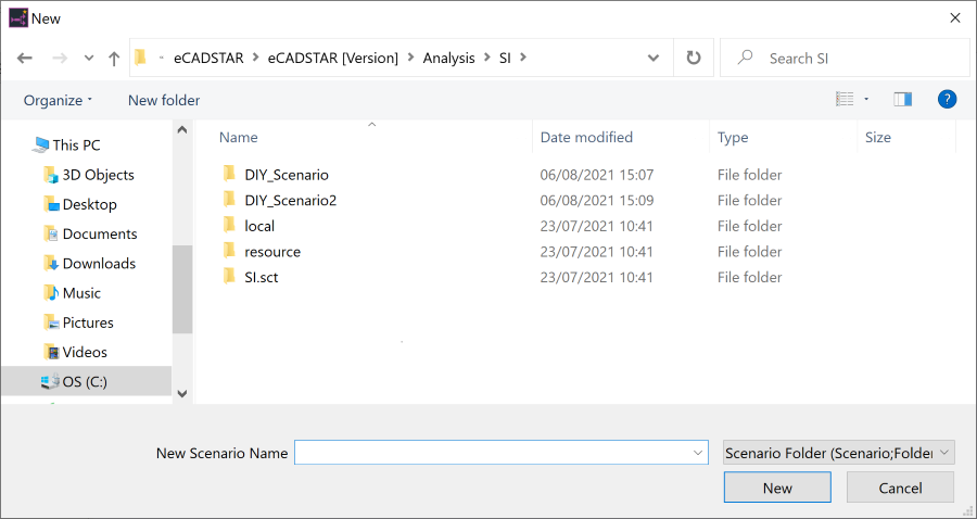
- In the New Scenario Name box, type the following path “C:\Users\Public\eCADSTAR\eCADSTAR [Version]\Analysis\SI\DIY_Xtalk” and click New. Scenario data is created and "DIY_Xtalk.sidf" is shown on the title bar.
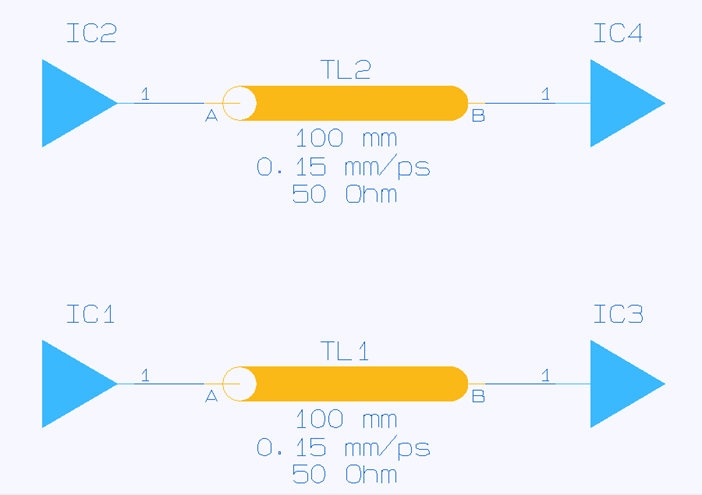
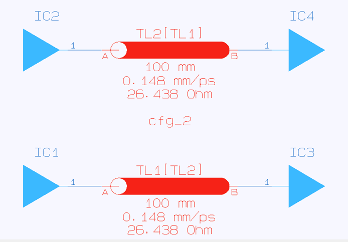
- Enter two pairs of topologies for one-to-one connections as shown below. Set the length of the transmission line to "100" (mm).
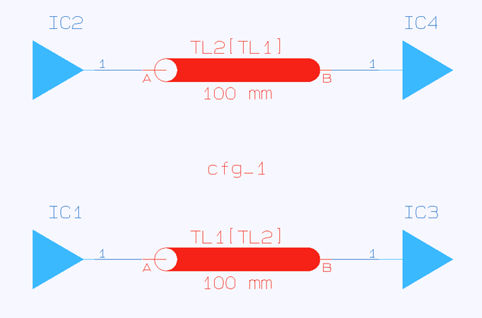
- Couple the transmission lines as follows:
- Select either of the transmission lines, and then select the other by pressing the Ctrl key.
- Right-click, and select Coupled on the assist menu. The coupled transmission line name is shown in square brackets ([ ]).
- Change the cutting plane structure as follows:
select the symbol of a transmission line and click
 Edit Config on the toolbar. The Configuration Editor is displayed.
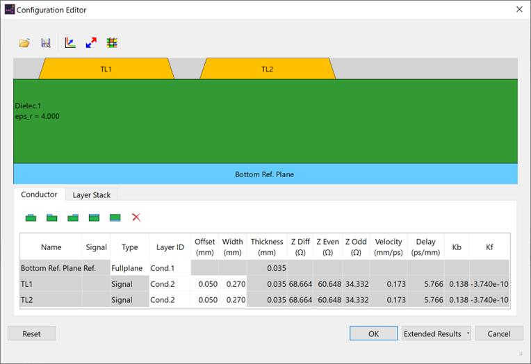
- The Configuration Editor allows you to define the cutting plane structures of tracks. Do this as follows.
- Add a dielectric layer above a conductor layer by switching to the Layer Stack
tab, and then clicking
 Insert row above.
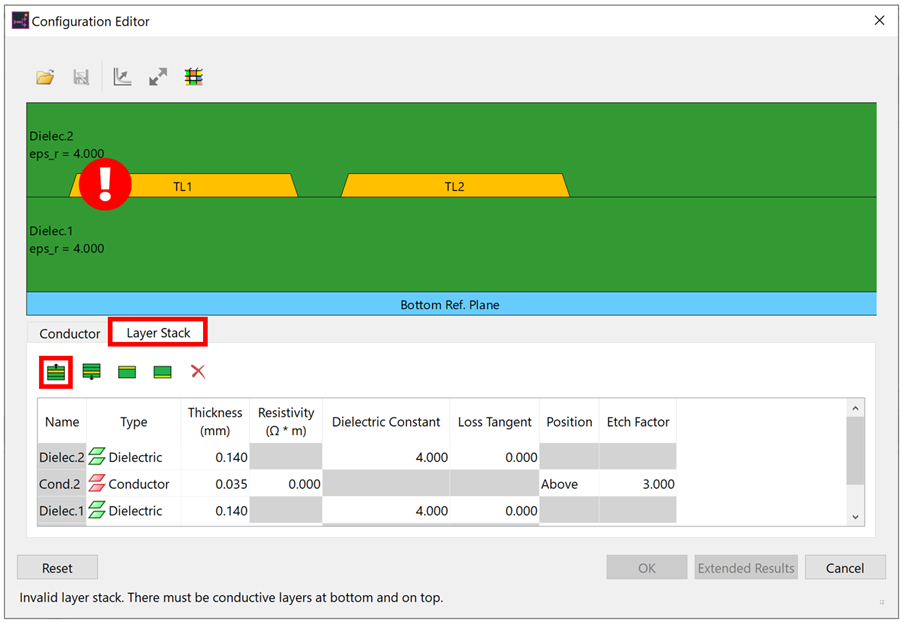
A new dielectric layer is inserted above the selected conductor layer. Note that this layer stack is not valid. This is indicated by the exclamation mark on the display.
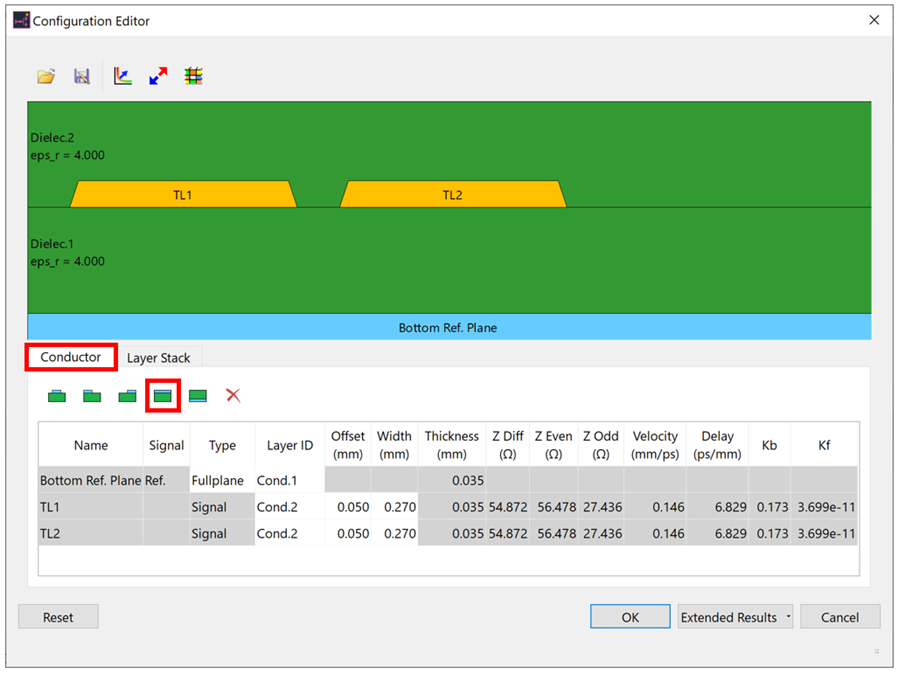
- Click the Insert row button that is highlighted above. A new conductor layer is inserted above the selected dielectric layer. Note that the exclamation mark has gone. This indicates that the layer stack is now valid.

- Next, add a top plane as follows: Switch to the
Conductor tab, and click
 Top Ref. Full Plane.
A top plane is added, the structure is changed to stripline and the impedances are recalculated.
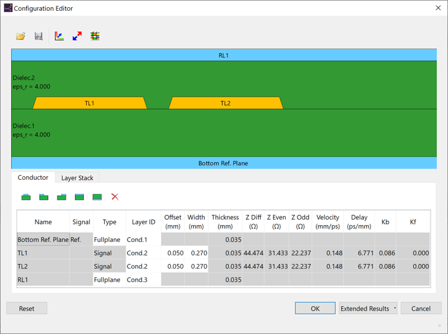
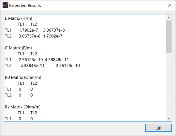
- Click Extended Results to launch the field solver. The RLGC matrix is calculated, as well as modal items, and differential impedance.
- Click OK to close Configuration Editor. The values calculated with the field solver are applied to the transmission lines.
- On the toolbar, execute
 SI Analysis. If prompted to save,
then click OK. A default model and
stimulus are automatically assigned to perform SI analysis.
SI Analysis. If prompted to save,
then click OK. A default model and
stimulus are automatically assigned to perform SI analysis.
- To define an input waveform for a driver to be regarded as the victim, select a driver symbol in Electrical Editor.
- On the assist menu, click Set Stimulus.
- Select "Z_Constant_L" in the Stimulus dialog, and click OK. "Z_Constant_L" indicates a constant voltage on the Low side.
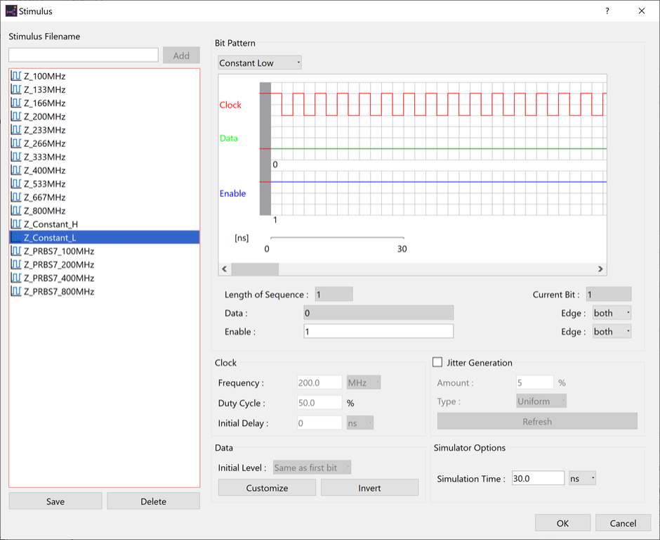
By setting a constant voltage on the Low side, the degree of impact from the other signal can be easily checked.
- On the toolbar, executeSI Analysis again. If prompted
to save, then click OK.
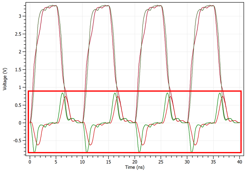
- Check the crosstalk to which the aggressor is subjecting the victim.
- Close eCADSTAR Analysis Result Viewer.
This task is demonstrated in the following video.
