
Placing a Termination Resistor
This topic describes how to place a Termination Resistor in Electrical Editor.
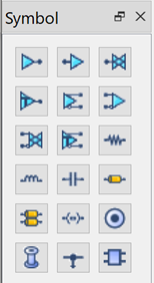
- In Electrical Editor, click the resistor symbol in the Symbol panel, and drag it onto the canvas.
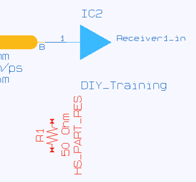
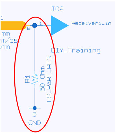
- Right-click to launch the assist menu, and then select Rotate > Rotate 90 Deg (CounterClockWise). Place the resistor near to the receiver pin as shown below. By default, this is a "50 Ohm” resistor.
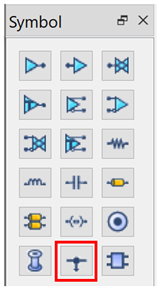
- In the Symbol panel, click the Power/GND symbol and drag it onto the canvas.
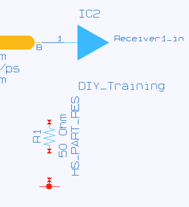
- Right-click to launch the assist menu, and select Rotate > Rotate 90 Deg (CounterClockWise). Repeat this step to rotate the symbol by 180 degrees.
- Place the Power/GND symbol as shown below.
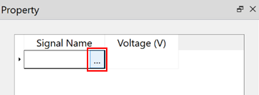
- Ensure that the Power/GND symbol is selected on the canvas.
- In the Property
panel, place the cursor over the Signal
Name cell, and click the displayed
 button. The Voltage List dialog is
displayed.
button. The Voltage List dialog is
displayed.
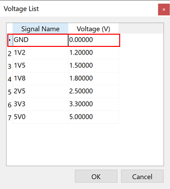
- In the Voltage List dialog, select "GND" and click OK to close the dialog.
- Connect the power/GND and resistor symbols on the receiver side, as shown below.
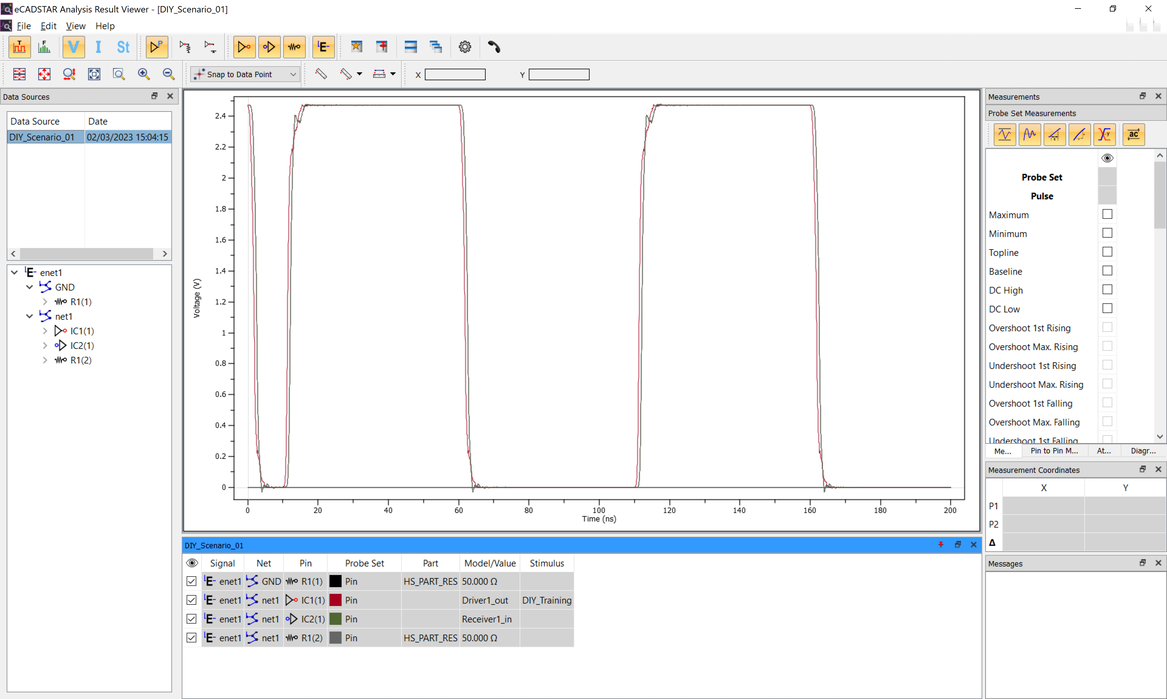
- On the menu bar, click Tool > SI Analysis.
- Click OK in the displayed confirmation dialog to continue. The simulation process is started, and eCADSTAR Analysis Result Viewer is displayed with the result of the simulation. The termination resistor has reduced the ringing in the waveform.
- Close eCADSTAR Analysis Result Viewer.
This task is demonstrated in the following video.
