
Applying a Topology
This topic describes how to apply a topology in Electrical Editor.
- In the Electrical Editor menu bar, click File > New. The New dialog is displayed.
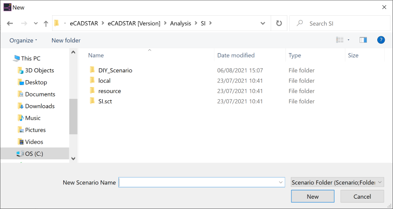
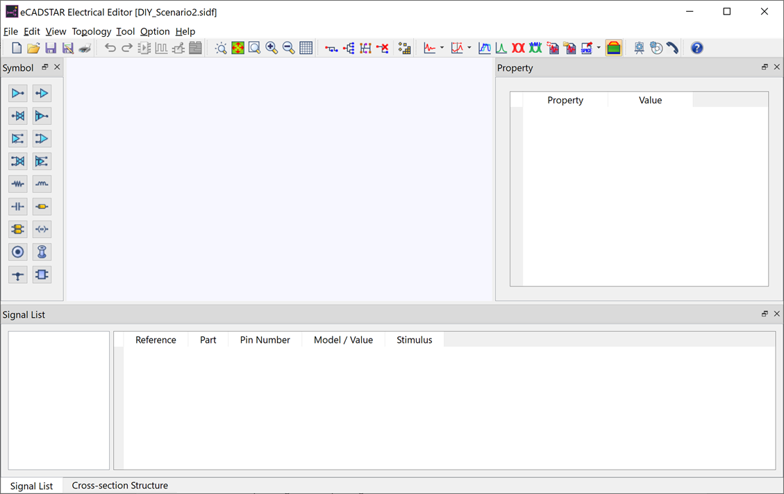
- In the New Scenario Name box, type the following path: “C:\Users\Public\eCADSTAR\eCADSTAR [Version]\Analysis\SI\DIY_Scenario2” and click New. Scenario data is created, and "DIY_Scenario2.sidf" is shown in the title bar.
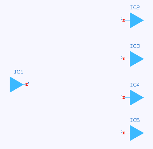
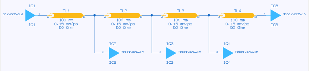
- In the Symbol panel, place one driver and four receivers in suitable locations, as shown below.
The local simulation library must be populated for this scenario. Import the SI_models.ixf file in the eCADSTAR Simulation Library Browser within Electrical Editor.
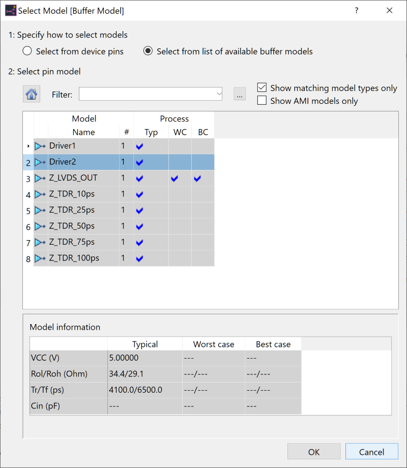
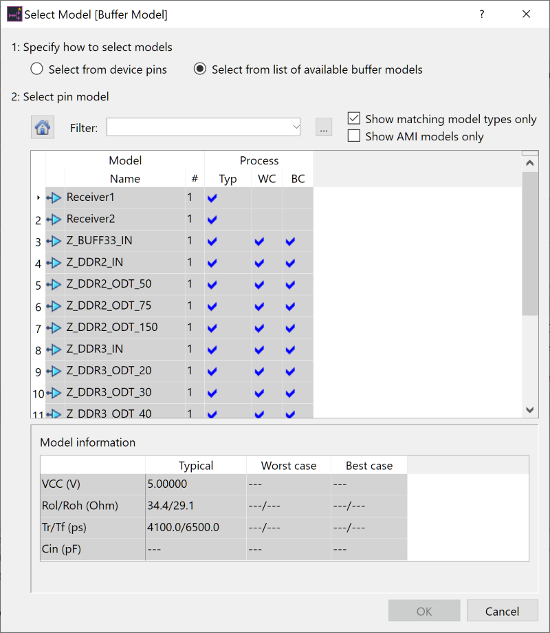
- Select the driver as follows: open the Select Model dialog from the Model field in the Property panel, and apply "Driver2".
- In the Stimulus filename
box in the Property panel click
 to open the Stimulus dialog.
 - Enter the name “DIY_Training”, and click Add. The stimulus filename is added to the list of available stimuli.
- For the DIY_Training stimulus, enter the parameters shown in the following image.
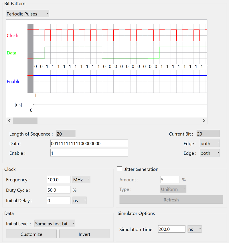
- Click Save to save the details of the stimulus.
- Click OK to assign the stimulus to the scenario.
- On the canvas in Electrical Editor, select all receiver symbols.
- Open the Select Model dialog from the Model box in the Property panel, and apply "Receiver2".
- On the toolbar, click
 Daisy chain.
 - Click OK in the displayed confirmation dialog. The topology is now a daisy chain.
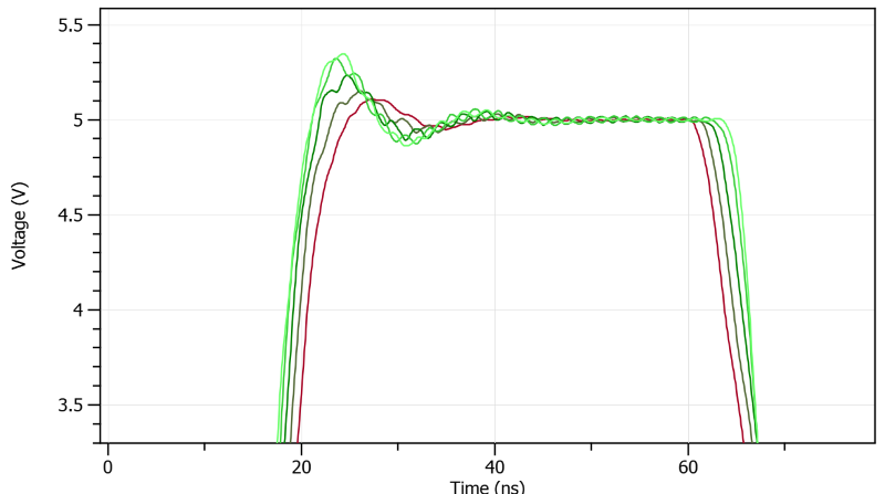
- On the toolbar, click
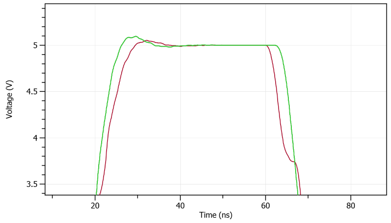
 SI Analysis. You can see that the time
to arrive differs between the receivers.
SI Analysis. You can see that the time
to arrive differs between the receivers.
- Close eCADSTAR Analysis Results Viewer.
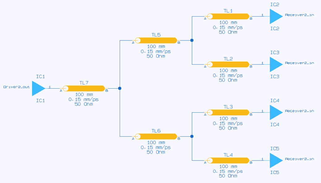
- On the Electrical Editor toolbar, click
 H-Tree and then
click SI
Analysis. The delay at the receivers is minimized.
H-Tree and then
click SI
Analysis. The delay at the receivers is minimized.
- Close eCADSTAR Analysis Results Viewer.
This task is demonstrated in the following video.
