
SPICE Controller Tools in Schematic Editor
Netlist Out
Netlist Out for SPICE Controller uses the properties of components in a schematic to create a netlist for the analog simulator. The netlist file is created with the name <Circuit name>.adn in the folder named simA, in the same directory as the schematic folder.
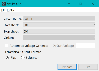
- Start/Stop sheet: sets the range of sheets that are included in the netlist out for SPICE. If you want to see only certain sheets, then the sheets must be reordered.
- Variant: if you are using a variant design, then you can choose the variant to create the netlist from. This will impact the nets used, as well as the various components.
- Automatic Voltage Generator: you can use voltage supply symbols with single pins when performing simulations. If the single pin with the voltage supply (component type: Power) symbol is included in the schematic data, then add the voltage supply to the net list. The numerical information about the voltage value is automatically acquired from the part name of the voltage supply symbol. If it cannot be acquired, then the value specified for the default voltage is output.
- Hierarchical Output Format
- Flat: hierarchical circuits are output to <circuit_name>.adn in flat format. For components in the highest hierarchy, the properties that are input are used.
- Subcircuit: hierarchical circuits are output to the files <circuit_name>.adn and <lower_circuit_name>.inc in subcircuit format. For <circuit_name>.adn, nets in the highest hierarchy and Instance hierarchy are output.
Pin Table Resource Editor
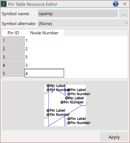
By default for Netlist Out, the node numbers for symbol to SPICE model mapping are determined by the symbol Pin ID property. This results in mapping 1-1, 2-2, 3-3, etc. However, a pin table resource can be used to define a consistent symbol pin mapping to node order, within the SPICE model.
Note
- Setting the symbol Pin ID to SPICE model Node Number in the Pin Table Resource Editor panel is a global definition. It is set for all instances of the symbol in the schematic design.
- The Pin Table Resource Editor panel is populated by sending a selected symbol from the Library Searcher panel.
