
Starting the PI/EMI Analysis Module
This topic describes how to launch the PI/EMI analysis module, and configure the display and view settings. When the PI/EMI analysis module is launched, the following actions are executed.
- All area fill data of the same net is merged.
- Component types are recognized.
- Attributes for signals are recognized.
- Information such as layer configuration is recognized.
After launching this module, you can continue operating other eCADSTAR tools. However, the above actions are only executed when the PI/EMI analysis module is next launched.
- On the ribbon in eCADSTAR PCB Editor, click Analysis > PI/EMI > PI/EMI Analysis.
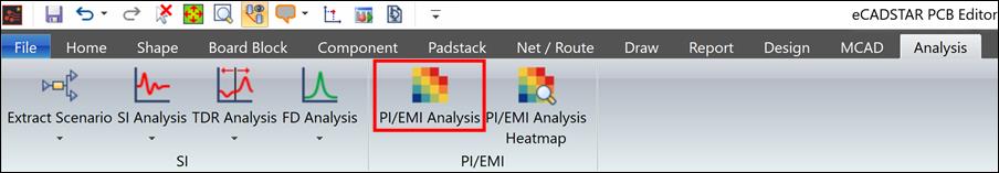
The PI/EMI Analysis module is launched.
- Close the Supply Pin Type Report dialog that appears.
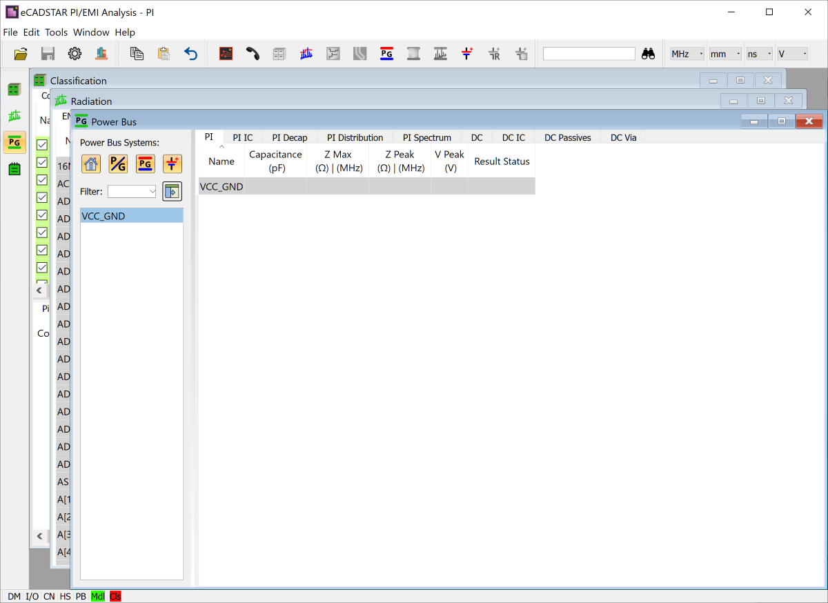
Display Settings
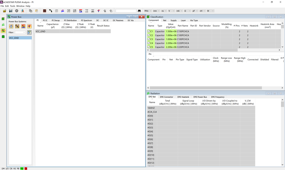
Configure the display and view settings as follows. The PI/EMI analysis module comprises four views (windows). Each view displays result, classification or analysis information.
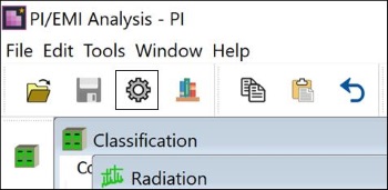
- On the PI/EMI Analysis module toolbar, click
 Options.
The Options dialog is displayed.
Options.
The Options dialog is displayed.
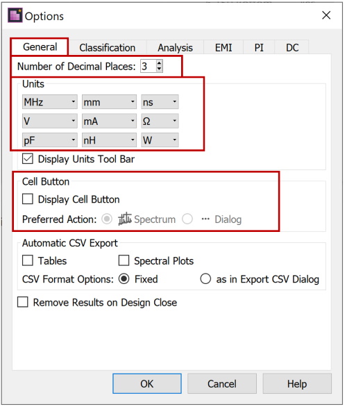
- In the Options dialog, General tab, set the values shown in the image below.
- Number of Decimal Places: sets the number of decimals.
- Units: sets the units for each cell (attribute or analysis result).
- Preferred Action: specifies the action associated with double-clicking in a results cell.
- Cell Button: controls the display of the button which launches an additional dialog from within a cell.
- Click OK to close the Options dialog.
- On the menu bar of the PI/EMI Analysis module, select Window > Tile to check the outline of the views.
This task is demonstrated in the following video.
