
The Design Settings dialog
allows you to set design values that apply to relevant commands in eCADSTAR PCB Editor.
Click Settings in an appropriate command
dialog to display the relevant category in the Design
Settings dialog. Alternatively, display the Design
Settings dialog by clicking Design >
Settings >  Design or Net
/ Route > Design Settings >
Design or Net
/ Route > Design Settings >  Routing Settings on the eCADSTAR PCB Editor
ribbon.
Routing Settings on the eCADSTAR PCB Editor
ribbon.
Dimension Text
Precision (Dimension)
| Value | Description |
|---|---|
| 0-5 | Specify the number of decimal places for the dimension value. |
Precision (Tolerance)
| Value | Description |
|---|---|
| Same as dimension. | Sets the number of decimal places for the tolerance value to be the same as for the dimension value. |
| 0-5 | Specify the number of decimal places for the tolerance value. |
Zero suppression
| Value | Description |
|---|---|
| Never | Zeros are never suppressed in the dimension value. For example: "0.100" is displayed when the precision is 3. |
| Decimal only | Zeros are only suppressed in the decimal part of the dimension value. For example: "0.1". |
| Integer only | Zeros are only suppressed in the integer part of the dimension value. For example: ".100". |
| Both | Zeros are suppressed for the decimal and integer parts of the dimension value. For example: ".1". |
Offset from dimension
| Value | Description |
|---|---|
| Real number equal to or greater than 0. | Specify an offset value from the dimension line to the dimension string. |
Font
| Value | Description |
|---|---|
| (Font values) | Select a single byte font for the text that is used to display dimensions. |
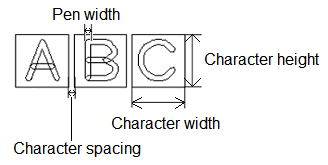
Character width
| Value | Description |
|---|---|
| Real number greater than 0. | Set the width for text characters (real number equal to or greater than 0). You can also select this from the Font setting dialog. This value refers to the dimensions of the non-displayed box which contains the character, rather than the actual width of the character. |
Character height
| Value | Description |
|---|---|
| Real number greater than 0. | Set the height for text characters (real number equal to or greater than 0). You can also select this from the Font setting dialog. This value refers to the dimensions of the non-displayed box which contains the character, rather than the actual height of the character. |
Character spacing
| Value | Description |
|---|---|
| Real number greater than 0. | Set the spacing for text characters (Real number equal to or greater than 0). You can also select this from the Font setting dialog. This value refers to the spacing between the non-displayed boxes which contain the characters, rather than the actual spacing between characters. |
Select font sizes
| Value | Description |
|---|---|
| Select | Displays the Font setting dialog. This contains the text size and spacing criteria that you define for eCADSTAR PCB Editor or Footprint Editor. Select a row in the dialog, and click Apply or OK to apply the settings to the Design Settings dialog. Existing values in the Design Settings dialog are overwritten by the values that you specify. |
Origin
| Value | Description |
|---|---|
| (Justification) | Specify the reference point for characters from the following
options. The origin is shown as a red point on the image that
accompanies each option.
|
When you add text in eCADSTAR, each character is placed within a box, which is not displayed. The values that you specify in the above section refer to the dimensions of this box, rather than the dimensions of the characters. The actual dimensions of characters will vary, depending on their position within this box. This is illustrated in the following image.
Dimension Display
Arrow Length L
| Value | Description |
|---|---|
| Real number greater than 0. | Set the length of the arrow "head".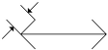 |
Arrow Angle A
| Value | Description |
|---|---|
| Integer between 1 and 90. | Set the angle of the arrow "head".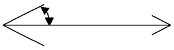 |
Circle diameter D
| Value | Description |
|---|---|
| Real number greater than 0. | Set the diameter of the circle associated with an arrow.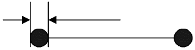 |
Offset dimension O1
| Value | Description |
|---|---|
| Real number equal to or greater than 0. | Set the offset value shown below for a dimension line.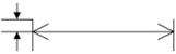 |
Offset aux line O2
| Value | Description |
|---|---|
| Real number equal to or greater than 0. | Set the space for starting an extension line from the dimension
reference point.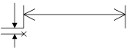 |
Line width
| Value | Description |
|---|---|
| Real number equal to or greater than 0. | Set the pen width for drawing dimension lines. |
Subtract Parameter
Allow isolated figure
| Value | Description |
|---|---|
| Selected | A copper area is generated for an area that becomes isolated as a result of correction. |
| Not selected | A copper area is not generated for an area that becomes isolated as a result of correction. |
Closed area generation
| Value | Description |
|---|---|
| Selected | An area is generated within the target shape, even when the target shape for DRC error avoidance has a loop shape that is created by a closed line. |
| Not selected | When the target shape for DRC error avoidance has a loop shape that is created by a closed line, an area is not generated within the target shape. |
Text viewed as
| Value | Description |
|---|---|
| True shape | The area flood will fill to within the clearance rules of text. |
| Rectangle | A rectangle is drawn around the extents of the text. This prevents area flood from filling in this area. |
Connect to no net
| Value | Description |
|---|---|
| Selected | An object with no net will be connected to an area fill that has a net when it is generated. |
| Not selected | An object with no net will be isolated from an area fill that has a net when it is generated. |
Connect to no net in component
| Value | Description |
|---|---|
| Selected | A figure within a component that has no net will be connected to an area fill that has a net when it is generated. |
| Not selected | A figure within a component that has no net will be isolated from an area fill that has a net when it is generated. |
Merge distance
| Value | Description |
|---|---|
| Real number equal to or greater than 0. | Specify the distance for which target objects are merged into
one object to prevent DRC errors. This is measured between the center points of objects. |
Minimum area
| Value | Description |
|---|---|
| Real number equal to or greater than 0. | For new template areas, this setting allows you to specify
the minimum area of copper that is generated, by default. If the
area of the copper area is less than the specified value, then
it is not generated. Specifying a minimum area for template areas
allows you to prevent isolated copper areas being generated.
Note
|
If an area fill shape for a template area is cut into multiple shapes when copper is repoured, then the above Subtract Parameter settings are not applied to the newly-created area fills. Instead, the settings in the Template Parameters dialog are applied.
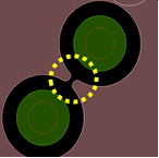
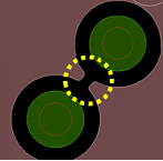
This setting controls the minimum width of the spacing when the clearance of two objects overlaps and creates a gap.
| Value | Description |
|---|---|
| Selected | When figures are subtracted, the Min. spacing setting within the area fill is maintained. This is shown in the following example. Min. spacing set to 0.2mm
Min. spacing set to 0.4mm
If Gap correction is selected, then the Min. spacing box is made available. |
| Not selected | When figures are subtracted, the gap between the area fills is not changed. |
Min. spacing
Select whether the clearance within the same area fill uses a rule, or the minimum spacing that you specify.
| Value | Description |
|---|---|
| Rule | The clearance within the same area fill is specified using the rule in the Rule Editor Dialog. The Specified value box is made unavailable. |
| Specified value | The Specified value box is made available. The value that you enter in this box is used as the minimum spacing within the same area fill. |
Specified value
| Value | Description |
|---|---|
| Real number equal to or greater than 0. | When Min. spacing is set to Specified value, enter a value to set the minimum spacing within the same area fill. If you enter "0", default rule specified in the Rule Editor Dialog is used. |
Min. width correction
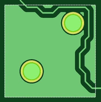
This setting controls the minimum width of a copper pour area between objects, such as two components, or a component and the edge of the template area. It allows you to maintain a minimum width value for these gaps by changing the minimum width value, Min. width. Set this in the Rule Editor Dialog or in the Specified value box below.
These default settings can be overridden for a particular template area in the Template Parameters Dialog.
| Value | Description |
|---|---|
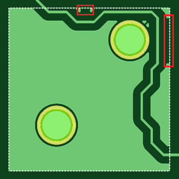
| Selected | If the Min. width value for gaps within the same area is not sufficient because of the track width used to create the area, then the Min. width value is maintained by changing it for the gap. This is illustrated below using increasingly large Min. width values. Set to 0.1mm: the width between components and the edge of the template area is above the minimum width. Therefore, no changes are made.
Set to 0.3mm: the width between components and the edge of the template is below this minimum width. Therefore, changes are made to increase the minimum width of the copper pour area in the positions marked below.
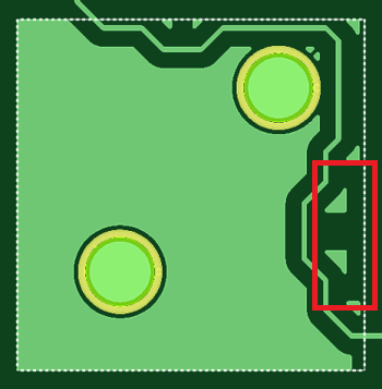
Set to 1.0mm: the width between components and the edge of the template is below this minimum width. Therefore, changes are made to increase the minimum width of the copper pour area in the positions marked below.
Note In this example, small triangular sections remain because Allow isolated figure is selected in the Template Parameters Dialog. If Min. width correction is selected, then the Min. width box is made available. |
| Not selected | When figures are subtracted within the same area, the Min. width value of tracks is not changed. |
Min. width
| Value | Description |
|---|---|
| Rule | The minimum gap width specified in the Rule Editor Dialog is set as the minimum clearance. |
| Specified value | The Specified value box is made available. The value that you enter in this box is used as the minimum gap. |
Specified value
| Value | Description |
|---|---|
| Real number equal to or greater than 0. | If Min. width is set to Specified value, then enter a value for the minimum gap width. If you enter "0", then the default clearance rule specified in the Rule Editor Dialog is used. |
Thermal Relief
Number of lines
| Value | Description |
|---|---|
| Integer greater than or equal to 0, and less than or equal to 12. | Specify the number of thermal lines to be generated. |
Track width
| Value | Description |
|---|---|
| Real number equal to, or greater than 0. | Specify the track width of the thermal line to be generated. |
Track start angle
| Value | Description |
|---|---|
| Real number equal to or greater than 0, but smaller than 360. | Specify the start angle of the thermal track to be generated. |
Additional Spacing
| Value | Description |
|---|---|
| Real number equal to, or greater than 0. | Specify a value for extra spacing between the thermal lines. This is additional to the spacing that is set in the design rules. |
Pin
| Value | Description |
|---|---|
| Selected | Thermal lines are generated between both through hole pins and surface mount pins that are in the same net as the conductor area to be generated. |
| Not Selected | Thermal lines are not generated between either through pins or surface mount pins that are in the same net as the conductor area to be generated. |
Via
| Value | Description |
|---|---|
| Selected | Thermal lines are generated between vias that are in the same net as the conductor area to be generated. |
| Not Selected | Thermal lines are not generated between vias that are in the same net as the conductor area to be generated. |
For area fill shapes on a template layer, which have a paired conductor layer: If the area fill shape is cut into multiple shapes, then the above Thermal Relief settings are not applied to the newly-created area fills. Instead, the settings in the Template Parameters dialog are applied.
Online DRC
This section allows you to specify targets for the Online DRC command. This command allows
you to automatically check clearances while making changes to a design.
See Executing
DRC while Editing a Design. The Online
DRC section is displayed by clicking Report
> Design Rule Checking >  Online DRC split
button > Online DRC Settings on the
eCADSTAR PCB Editor
ribbon. Alternatively, select Online DRC split button > Online DRC Settings on the status
bar.
Online DRC split
button > Online DRC Settings on the
eCADSTAR PCB Editor
ribbon. Alternatively, select Online DRC split button > Online DRC Settings on the status
bar.
Check Components
| Value | Description |
|---|---|
| Selected | Routing patterns and components are checked. |
| Not Selected | Only routing patterns are checked. Components are not checked. |
Pin Shape
| Value | Description |
|---|---|
| Selected | Clearances of pin shapes on the component are checked. |
| Not Selected | Component pins are not checked. Clearances of component areas are checked. |
Component Position
| Value | Description |
|---|---|
| Selected | Components are checked for the violation of limits on placement side, and placement angle. |
| Not Selected | The limits on the placement side and placement angle are not checked. |
Component placement (manhattan length)
| Value | Description |
|---|---|
| Selected | In a High Speed environment, the manhattan length of pin pairs
is checked.
Note In Constraint Browser, the actual routed length of the pin pair is checked, rather than the manhattan length. This value is shown in the Actual column, in the High Speed Routing Tab, Pin Pair Length section. |
| Not Selected | In a High Speed environment, the manhattan length of pin pairs is not checked. |
Resist check
This setting affects template areas. You can override it for a selected template area using the Resist check box in the Template Parameters Dialog. The setting specified in the Template Parameters Dialog is applied without regenerating the template area.
When adding template areas to conductor layers
Existing template areas are not automatically updated if you change this setting, or add a new template area. Also, this default setting is not applied automatically if all conductor areas are repoured. To change the status of multiple existing template areas:
- Select the relevant template areas on the canvas, or by selecting them in the Template Area List.
- Launch the Template Parameters Dialog, and set the Resist setting as required.
- Repour all conductor areas to update the template area clearances. This is not required if Automatic Repour is selected in the Template Area Settings Dialog.
When adding template areas to template layers
If you add template areas to template layers or conductor layers, then the clearance rule is set by this setting, and the Template Parameters Dialog setting reflects this. If you change the Resist check setting and repour, then the Template Parameters Dialog setting is also changed and the clearance is updated.
However, if you change the Template Parameters Dialog setting for template areas on a template layer (including opening the dialog, making no changes and then clicking OK), then this setting must be manually changed thereafter. This is the same functionality as for a template area on a conductor layer.
| Value | Description |
|---|---|
| Selected | If selected, then the clearance from resist objects is applied that is set in the Rule Editor Dialog: Non Conductor Tab when adding a copper area. This is done when the Online DRC command is toggled on or off. By default, existing copper areas are not affected. |
| Not Selected | The clearance from resist objects is not applied when adding a copper area. By default, existing copper areas are not affected. |
For same net
| Value | Description |
|---|---|
| Selected | The clearance from resist objects is maintained when routing
patterns are edited. However, the following are not checked:
|
| Not Selected | For a pattern that overlaps with a resist object, lines and areas are not checked that are in the same net. |
Via check for same net
| Value | Description |
|---|---|
| Selected | Vias are added or edited while maintaining the clearance from other vias in the same net. |
| Not Selected | Vias in the same net are not checked with each other. |
Hole to hole
| Value | Description |
|---|---|
| Selected | Vias are not added in positions where via holes in the same net cannot keep the via hole clearance. |
| Not Selected | Vias are not added in positions where via land shapes overlap each other. |
Allow stack via
| Value | Description |
|---|---|
| Selected | A via can be added just above or below the via in the same
coordinate position, in the same net. Vias cannot be added that have a From-To combination which violates the via combination restriction. |
| Not Selected | Vias are added while maintaining the clearance from other vias in the same net. |
Post Check
This section allows you to specify the parameters for
the Post Check command. It is displayed
by clicking Report > Design Rule Checking
>  Post Check split button > Post Check
Settings on the eCADSTAR PCB Editor
ribbon. Alternatively, select Post Check split
button > Post Check Settings on the
status bar. The Post Check command allows
you to allows you to automatically check clearances after you make
changes to a design on the canvas. See Executing
DRC while Editing a Design.
Post Check split button > Post Check
Settings on the eCADSTAR PCB Editor
ribbon. Alternatively, select Post Check split
button > Post Check Settings on the
status bar. The Post Check command allows
you to allows you to automatically check clearances after you make
changes to a design on the canvas. See Executing
DRC while Editing a Design.
Show DRC results after check
Allows you to specify whether DRC errors are displayed immediately after making a change to a design.
| Value | Description |
|---|---|
| Selected | DRC errors are displayed immediately after making a change to a design. |
| Not selected | DRC errors are not displayed immediately after making a change to a design. |
Check Components
Allows you to specify whether DRC errors are displayed immediately after making a change to a design.
| Value | Description |
|---|---|
| Selected | Routing patterns and components are checked. |
| Not selected | Only routing patterns are checked. Components are not checked. |
Cross Probe
For an object that is displayed on the canvas using the Auto Send command, or by clicking
a component in the Component
Selector dialog, Reference Designator
section list. This section allows you to
specify its position and size. It is displayed by clicking Design
> Cross Probing >  split button
  Cross Probing Settings on the eCADSTAR PCB Editor
ribbon. Alternatively, click split button > Cross Probing Settings on the status bar.
You can also display this section by clicking Cross
Probe Settings in the Component
Selector dialog.
Cross Probing Settings on the eCADSTAR PCB Editor
ribbon. Alternatively, click split button > Cross Probing Settings on the status bar.
You can also display this section by clicking Cross
Probe Settings in the Component
Selector dialog.
- These settings do not apply to items that are selected in the Component Selector dialog.
- If you cross probe a large number of items, then a confirmation dialog may be displayed which warns you that the process may take a long time. Click Yes in the displayed dialog to continue
Cross Probe
| Item | Description | |
|---|---|---|
| Select only | If an object is selected from outside of the canvas, then its position and size are not changed when highlighted on the canvas. | |
| Centering | If an object is selected from outside of the canvas, then it is highlighted in the center of the canvas. Its size is not changed. | |
| Adjust | If an object is selected from outside of the canvas, then you can specify its size when highlighted on the canvas. This is done using the Adjust ratio (%) box. If Adjust is selected, then this box is made available. | |
| Adjust ratio (%) | Specify a zoom ratio using an integer between 1 and 100, where 100 is fully zoomed in. This box is made available when Adjust is selected. |
Snap
Allows you to configure the Snap
function (2D View mode only) in eCADSTAR PCB Editor.
This function is used to snap to existing objects on the canvas when running
a command. When the position of an object on the canvas is identified,
the "Flag" icon is displayed and the cursor is snapped to its
coordinates. When the Snap command
is toggled on, the following icon is displayed at the cursor position:
 .
This section of the Design Settings dialog
is displayed by clicking the Snap
split button on the status bar and then selecting Snap
Settings.
.
This section of the Design Settings dialog
is displayed by clicking the Snap
split button on the status bar and then selecting Snap
Settings.
Snap
| Value | Description | |
|---|---|---|
| Only allow snap point selection | Allows you to specify whether a snapping position must be identified before a relevant command can be run. | |
| Selected | The relevant command cannot be executed unless a snapping position is identified. | |
| Not Selected | The relevant command can be executed, regardless of whether a snapping position is identified. | |
| Multiple Pad/Padstack reference points | For a non-circular pad or padstack, this setting allows you to snap only to its center, or to the vertices and mid points of its segments, as well as to its center. | |
| Selected | For a non-circular pad or padstack, you can snap to its center,
as well as to its vertices and the mid points of its segments.
These snap points are illustrated below for a rectangular padstack.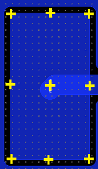 | |
| Not Selected | For a non-circular pad or padstack, you can snap only to its
center. This snap point is illustrated below for a rectangular
padstack.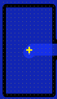 |
Arc
Allows you to snap to the middle point, center point or corner point of an arc.
| Value | Description |
|---|---|
| Middle point | If selected, then a flag icon is displayed at the middle point of the arc, and the cursor is snapped to it. |
| Center point | If selected, then a circle is displayed at the center point of the arc. This enables you to select this position when executing a command. |
| Corner point | If selected, then a flag icon is displayed at the corner of the arc or tangent arc. This marks the position a vertex would be if the arc was a 90 degree corner. The cursor is snapped to it. |
Target layer
Allows you to specify the layer for which the Snap function applies.
| Value | Description | |
|---|---|---|
| Visible layer | The Snap function applies to objects on the visible layer. | |
| Specify layer | The Snap function applies to objects on the layer that you select in the Layer box in the Target layer group. If selected, the Layer box is made available. | |
| Layer box | Specify the layer for which the Snap function applies. |
Objects
Allows you to select the type of object on the canvas for which the Snap function applies.
| Value | Description |
|---|---|
| Type | Select the type of object for which the Snap
function applies. The following types of object can be selected.
|
Routing
Snap between pins
| Value | Description |
|---|---|
| Selected | Route candidates are displayed between pins, and the rubber band is snapped when the cursor is placed over it. |
| Not Selected | No route candidate is displayed between pins. |
Snap to center
| Value | Description |
|---|---|
| Selected | The route is snapped only to the center between pins. |
| Not Selected | The route is selected from multiple candidates to be snapped between pins |
Space indicator
| Value | Description |
|---|---|
| Selected | A routing space is displayed as a guideline. The space is defined
by referencing the following items in sequence:
|
| Not Selected | The routing space is not displayed. |
No net routing
| Value | Description |
|---|---|
| Selected | Tracks that are not connected to a net can be added on the canvas. This allows you to add a track, and then add a net to it at a later time. |
| Not Selected | Tracks that are not connected to a net cannot be added to the canvas. |
Wide track snap mode
When joining tracks of different width, this setting allows you to specify whether they are snapped to their centers, or to either the center or outline of the narrower track.
| Value | Description |
|---|---|
| Center | When snapping between tracks of different width, the tracks
are snapped to their center lines. This is illustrated below.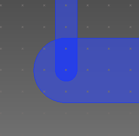 |
| Outline | When snapping between tracks of different width, the widest
track can be snapped to the outline of the narrower track. This
is illustrated below.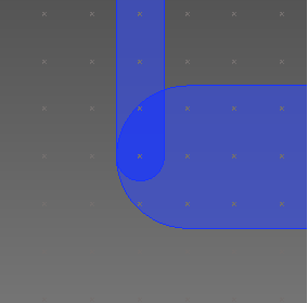 When Outline is selected, you can also snap to the center lines of the tracks. |
Trunking (Advanced)
Routing Parameters
Auto minimize crossed connection
| Value | Description |
|---|---|
| Selected | The order of routes in the trunk is automatically changed so that the number of intersecting unconnected routes at end points is minimized. |
| Not Selected | The order of routes in the trunk is not changed. |
Trunk corner style
| Value | Description |
|---|---|
| Octagonal | The corner that is added at a right angle is chamfered at 45
degrees. |
| Orthogonal | The corner that is added at a right angle is not changed. |
| Curved | The corner that is added at a right angle is filleted into
an arc. |
Trunk width change style
| Value | Description |
|---|---|
| Chamfer | The angle of the route connecting to the via pattern or rule
area is set to 45 degrees.
The following image shows a route connecting
to a via pattern.  The following image shows a route connecting to a rule area.  |
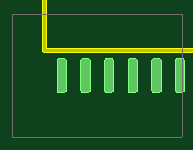
| Square | The angle of the route connecting to the via pattern or rule
area is set to 90 degrees.
The following image shows a route connecting
to a via pattern.  The following image shows a route connecting to a rule area. 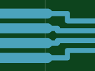 |
Guide Parameters
End routing area
| Value | Description |
|---|---|
| Selected | The termination routing area is displayed during routing. |
| Not Selected | The termination routing area is not displayed during routing. |
Twist arrow
| Value | Description |
|---|---|
| Selected | An arrow indicating the optimum entry direction that minimizes intersecting unconnected lines is shown at the snapping destination. |
| Not Selected | The optimum snap direction is not shown. |
Snap axis
| Value | Description |
|---|---|
| Selected | Axes are displayed from the center of the leading source and the snapping destination. |
| Not Selected | The snap axis is not displayed. |
Active snap
| Value | Description |
|---|---|
| Selected | When the cursor is placed near the snap axis, the cursor is automatically snapped to the axis. |
| Not Selected | Even if the cursor is placed near the snap axis, the cursor is not snapped to the axis. |
Single click finish on snap line
| Value | Description |
|---|---|
| Selected | When the target symbol  is displayed, clicking
the snap axis finishes the routing process. is displayed, clicking
the snap axis finishes the routing process.The target symbol is displayed when you can accept routing within Snap distance. |
| Not Selected | Clicking the snap axis does not finish the routing process. |
Snap axis length
| Value | Description |
|---|---|
| Small | The snap axis is set to have a short length. |
| Medium | The snap axis is set to have a medium length. |
| Large | The snap axis is set to have a long length. |
Snap distance
| Value | Description |
|---|---|
| Small | The snap axis is set to have a narrow recognition range. |
| Medium | The snap axis is set to have a medium recognition range. |
| Large | The snap axis is set to have a wide recognition range. |
Simple trunk view
| Value | Description |
|---|---|
| Selected | The trunk being routed is displayed in a simplified view (only
the trunk outline is displayed).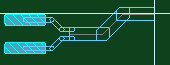 |
| Not Selected | The trunk being routed is displayed in a detailed view (the
trunk outline and its inner routes are displayed).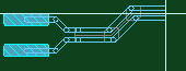 |
Composition parameters
Angled tracks tolerance
| Value | Description |
|---|---|
| Real number between 0 and 1.0. | Specify the tolerance angle for judging during composition whether or not the routes are parallel. |
Spacing tolerance
| Value | Description |
|---|---|
| Real number between 0 and 1.0. | Specify the tolerance for judging during composition whether or not the specified clearance is given between the parallel routes. |
Via pattern tolerance
| Value | Description |
|---|---|
| Real number between 0 and 25.4. | Specify the tolerance that is referred to for judging during composition whether the vias are in a group of via patterns. |
Ignore via pattern
| Value | Description |
|---|---|
| Selected | Vias are ignored during composition and only a trunk routing pattern is generated. |
| Not Selected | Vias are also trunked. |
Bus Route
Allows you to configure the guide parameters that are used by the Bus Route command.
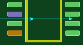
End Routing Area
Allows you to specify whether an end routing area is added around the destination pins.
| Value | Description |
|---|---|
| Selected | An end routing area is added around the destination pins. This
allows you complete the bus routing within a specified distance
from the destination pins, rather than at a set, close distance.
The Distance from target field
is made available, and allows you to specify this distance. In
the following image, End Routing Area
is selected. The bus routing
can be completed from this position.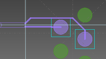 |
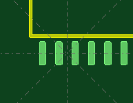
| Not Selected | An end routing area is not added around the destination pins.
This means that you must complete the bus routing at a set, close
distance form the destination pins. The Distance
from target field is made unavailable. In the following
image, End Routing Area is not selected. The bus routing can be
completed from this position.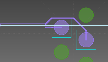 |
Distance from target
This field is made available when End Routing Area is selected. It allows you to complete the bus routing within the distance that you select from the destination pins.
| Value | Description |
|---|---|
| Small | Allows you to complete the bus routing when the bus outline is close to the destination pins. |
| Medium | Allows you to complete the bus routing when the bus outline is a medium distance from the destination pins. |
| Large | Allows you to complete the bus routing when the bus outline is a long distance from the destination pins. |
Twist arrow
| Value | Description |
|---|---|
| Selected | An arrow is displayed at the routing destination on the canvas
that indicates the optimum entry direction for completing the
end routing. The recommended direction minimizes the number of
intersecting signals. This is illustrated below.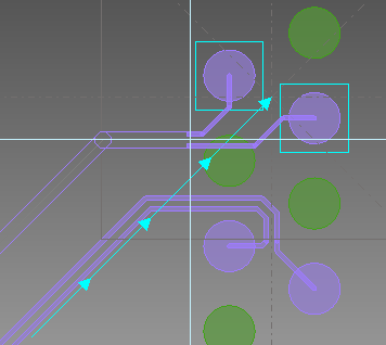 |
| Not Selected | The arrow that indicates the optimum entry direction for completing the end routing is not displayed on the canvas. |
Snap axis
| Value | Description |
|---|---|
| Selected | Axes are displayed at 45-degree increments from the center
of the end routing destinations. All fields in the Snap
axis section are made available.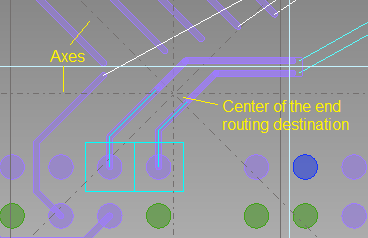 |
| Not Selected | The snap axes are not displayed. All fields in the Snap axis section are made unavailable. |
Active snap
| Value | Description |
|---|---|
| Selected | When you place the cursor near a snap axis, it is automatically snapped to it. |
| Not Selected | The cursor is not snapped automatically to the snap axis when placed near it. |
Single click finish on snap line
| Value | Description |
|---|---|
| Selected | If the target symbol is displayed on
a snap axis, then clicking the snap axis finishes the routing
process. The target symbol is displayed when you can accept routing
within the value specified in the Snap
distance field, in this section. |
| Not Selected | Clicking a snap axis does not finish the routing process. |
Snap axis length
Allows you to specify the length of the snap axes.
| Value | Description |
|---|---|
| Small | The snap axis is set to have a short length. This is the average track width multiplied by ten. |
| Medium | The snap axis is set to have a medium length. This is the average track width multiplied by twenty. |
| Large | The snap axis is set to have a long length. This is the average track width multiplied by forty. |
Snap distance
Allows you to specify the distance from the snap axes at which you can snap to them.
| Value | Description |
|---|---|
| Small | You can only snap to the snap axes when the cursor is half of the medium distance away from them. |
| Medium | You can snap to the snap axes when the cursor is a medium distance away from them. |
| Large | You can snap to the snap axes when the cursor is twice the medium distance away from them. |
Shielding
Snap
| Value | Description |
|---|---|
| Selected | When a shield is generated, pins, vias and area fills around the shield pattern are connected by lines. |
| Not Selected | When a shield is generated, nothing is snapped from the shield pattern. |
Delete isolation
| Value | Description |
|---|---|
| Selected | Shield patterns are deleted that have become isolated because of shield generation. |
| Not Selected | Shield patterns that have become isolated because of shield generation are not deleted. |
Fillet corner
| Value | Description |
|---|---|
| Selected | Bends in lines are generated as arcs. |
| Not Selected | Bends in lines are generated as vertices. |
Shape around pin
| Value | Description |
|---|---|
| Contour | A shield pattern which follows the shape of the pad is generated around the pin or via. |
| None | No shield pattern is generated around the pin or via. |
Minimum track length
| Value | Description |
|---|---|
| Real number equal to or greater than 0. | A shield pattern longer than the specified value is generated. (Specify the lower limit value of the shield pattern cut by an obstacle.) |
Shield merge
| Value | Description |
|---|---|
| Selected | If selected, shield signals are merged into appropriate, existing connections on the board, if possible. |
| Not Selected | Shield signals are not merged into existing connections on the board. |
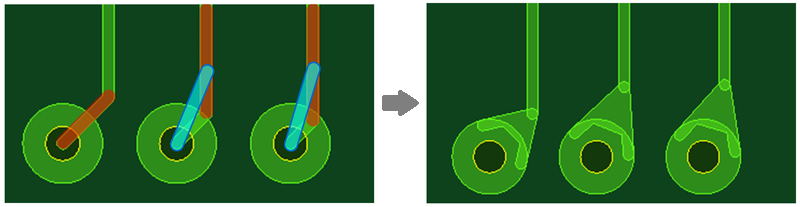
Teardrops
The following settings allow you to configure the teardrops that are created using the Reinforce command.
Teardrops
Maximum Length ratio
| Value | Description |
|---|---|
| Real number equal to or greater than 1.0. | Specify the maximum value for the length ratio of the teardrop.
This is the ratio between its length and width, as illustrated
below:
Length ratio = L / (R1 / 2)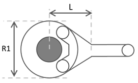 This value is used by the Reinforce command when you create teardrops. If DRC errors are produced, then this value is automatically adjusted down to the Minimum length ratio value. If teardrops cannot be created using the Minimum length ratio value, then an error is reported by the Reinforce command. Note If you specify a value in the Minimum length ratio box that is greater than the Maximum length ratio, then the Maximum length ratio value is automatically increased to this value. |
Minimum length ratio
| Value | Description |
|---|---|
| Real number equal to or greater than 1.0. | Specify the minimum value for the length ratio of the teardrop.
This is the minimum ratio between its length and width, as illustrated
below:
Length ratio = L / (R1 / 2) If the Minimum length ratio value for teardrops is not met, then the length of the teardrop is extended automatically to include the next segment of the track. If this value is still not met, then the teardrop is not created. Note Teardrops are not extended in this way for tracks connected as follows.
If teardrops cannot be created by the Reinforce command without producing DRC errors, then the Maximum length ratio value is automatically adjusted down to this value. If teardrops cannot be created using this value, then an error is reported by the Reinforce command. Note If you specify a value in the Minimum length ratio box that is greater than the Maximum length ratio, then the Maximum length ratio value is automatically increased to this value. |
Minimum line width ratio
| Value | Description |
|---|---|
| Real number greater than 1.0. | Specify the minimum value for the ratio between the widest
and narrowest widths of the teardrop. A teardrop is created when
the following condition is satisfied:
Widest width (R1) / Narrowest width (R2) >=
Minimum line width ratio. This is illustrated below.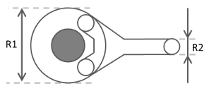 |
Extend to next segment
If the Minimum length ratio value for a teardrop is not met, then this setting allows you to automatically extend it to include the next segment of the track. It is selected by default. The setting that you specify is saved for the design, even after closing and reopening it.
Changes made to this setting affect only new teardrops that you create. To change existing teardrops, you must remove them and apply them again with the required setting.
| Value | Description |
|---|---|
| Selected | If the Minimum length ratio value for teardrops is not met, then the length of the teardrop is extended automatically to include the next segment of the track. This is done by adding a new auxiliary track. The length of the added track is equal to the Maximum Length ratio value. However, if the distance from the center of the pad to the closest available section of the track is shorter than the specified maximum, then the auxiliary track is connected to the end of the first track segment. The procedure for extending teardrops is illustrated below. The auxiliary track is shown in blue.
|
| Not Selected | If you try to reinforce a track which does not meet the minimum length ratio, then the teardrop is not generated and an error message is shown. The track must be moved in order to use a teardrop. |

Target
Surface mount pin
| Value | Description |
|---|---|
| Selected | Teardrops are generated on surface mount pins. |
| Not Selected | Teardrops are not generated on surface mount pins. |
Through hole pin
| Value | Description |
|---|---|
| Selected | Teardrops are generated on through hole pins. |
| Not Selected | Teardrops are not generated on through hole pins. |
Via/Pad
| Value | Description |
|---|---|
| Selected | Teardrops are generated in the via/pad. |
| Not Selected | Teardrops are not generated in the via/pad. |
Via Spirals
This section allows you to configure the settings for spiral vias.
Angle start
| Value | Description |
|---|---|
| An integer between 0 and 359. | Specify the start angle between the track and the first via.
Note 0 degrees is horizontal, at the 3 o'clock position. |
Angle increment
| Value | Description |
|---|---|
| An integer between 0 and 359. | For the angle of the track to be connected to the second and
subsequent vias that are generated: specify the amount by which
this angle is incremented, compared to the previous track.
The angle is incremented counter-clockwise
from the 3 o'clock position. |
Track length
| Value | Description |
|---|---|
| Real number equal to, or greater than 0. | Specify the minimum distance between consecutive vias. The distance is the center-to-center spacing in each via. |
Lengthen
This section allows you to specify the settings that are used by the Lengthen command. For the lengthening that is added to a routing pattern, select the meander mode and edge style, and specify the maximum size and minimum space. The specified settings are overridden by the settings in the Lengthening tab, in the Constraint Browser: Signals section, Signals tab or Constraint Browser: Signals section, Classes/Groups tab for a selected E-Net or E-Net class.
Meander mode
| Value | Description |
|---|---|
| Accordion | Lengthening is added to a selected routing pattern using the
accordion style. This is illustrated
below for the square edge style.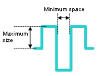 Specify the "Maximum size" and "Minimum space" settings shown above using the Max. size and Min. space fields, respectively, in this section. |
| Trombone | Lengthening is added to a selected routing pattern using the
trombone style. This is illustrated
below for the square edge style.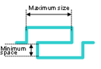 Specify the "Maximum size" and "Minimum space" settings using the Max. size and Min. space fields, respectively, in this section. |
Edge style
| Value | Description |
|---|---|
| Square | The angle of the segment end of the lengthen pattern is set
to 90 degrees. This is illustrated below for the Accordion
meander mode. This is illustrated below for the Trombone meander mode. |
| Chamfer | The angle of the route segment end of the lengthen pattern
is set to 45 degrees.
This is illustrated below for the Accordion
meander mode.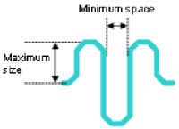 This is illustrated below for the Trombone meander mode. 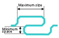 |
| Semicircle | The shape of the route segment end of the lengthen pattern
is set to an arc. This is illustrated below for the Accordion
meander mode.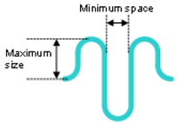 This is illustrated below for the Trombone meander mode. 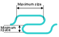 |
Max. size
| Value | Description |
|---|---|
| Real number equal to or greater than 0. | Set the maximum length applied between parallel routes when
lengthening a routing pattern.
This is illustrated below for the Accordion
meander mode.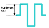 This is illustrated below for the Trombone meander mode. 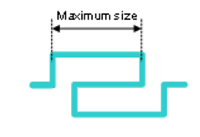 |
Min. space
| Value | Description |
|---|---|
| Real number equal to or greater than 0. | Set the minimum space applied between parallel routes when
lengthening a routing pattern.
This is illustrated below for the Accordion
meander mode.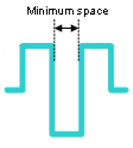 This is illustrated below for the Trombone meander mode. 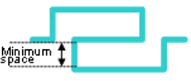 |
Re-lengthen at the end of interactive operations
| Value | Description |
|---|---|
| Selected | For signals that have length constraints set, the lengthening
patterns are reapplied after interaction with the signals in the
design. This maintains the integrity of the lengthening pattern,
and ensures that the length constraints are met. In a High Speed
environment, this is done at the end of the following operations.
|
| Not selected | For signals that have length constraints set, the lengthening patterns are not reapplied after interaction with the signals in the design. |
This dialog is used by the following commands.
Leader Dimension (Polygonal Line)
