
The Add Route command allows you to manually add a routing pattern while specifying the path (only available in 2D View mode). It is launched by clicking Net / Route > Routing > Add Route on the eCADSTAR PCB Editor ribbon. Alternatively, click Home > Add > Route on the eCADSTAR PCB Editor ribbon. For autorouting, refer to the Routing Strategy Help topic.
- The
following should be considered when routing a differential pair that
has a topology
template assigned.
In the Signals Tree, if you right-click the top level of the differential pair, and click Send Selection on the assist menu, then the entire differential pair is selected and displayed on the canvas. This allows you to start routing it using the Add Route command. However, when selecting a differential pair at this level, an incorrect Differential Pair Rule Stack may be applied to the transmission line which you start routing. This can create width and clearance errors in the routed tracks. To ensure that correct Differential Pair Rule Stacks are applied to each transmission line, follow one of these procedures. - In Constraint Browser, select the pin from which to start routing, and click Send Selection to select it on the canvas. Alternatively, manually select the differential pair on the canvas.
- If you send a differential pair to the canvas from Constraint Browser, then select Next Topology Pin Pair on the assist menu when you start routing. Alternatively, press the N key.
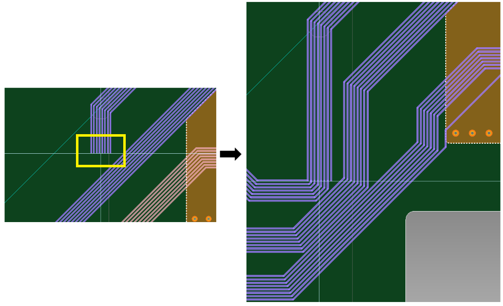
- If you create a layer exchange when routing a topology, then a Virtual Branch Point (VBP) will snap to the relevant via if within an appropriate distance from it. This occurs even if the topology is not completely routed.
Routing style
Specify the routing style as Activ-45, or select 45-degree, 90-degree or Free. When you start routing, the Routing style box is made unavailable.
| Value | Description |
|---|---|
| Activ-45 | Allows you to add tracks using the Activ-45 router. Tracks are added in 45 degree increments that follow the mouse trace. |
| 45-degree | The angle between the track segments to be added is limited to 0, 45, 90, 135, 180, 225, 270, and 315 degrees. |
| 90-degree | The angle between the track segments to be added is limited to 0, 90, 180 and 270 degrees. |
| Free | The angle between the track segments to be added is not locked. |
- When manual routing in the 45-degree or 90-degree modes, automatic pin swapping is limited to 2 pin passive components only. For any part other than a 2 pin passive part, use the Swap Pins or Swap Gates command to swap the pins or gates.
- When attempting to add vias though an invisible layer: if Automatic repour is selected for a copper flooded template, then note the following.
- Vias cannot be added when trunk routing, or routing in Activ-45 mode.
- Vias can be added when routing using the 45-degree, 90-degree or Free modes.
Push aside
Allows you to specify whether existing tracks are pushed aside by the track or trunk that you are routing. Tracks that are pushed aside conform to the design rules in the Rule Editor dialog. The Push aside functionality varies depending on whether Activ-45, or one of the 45-degree, 90-degree or Free options is selected. It also varies when routing a trunk. See Push aside mode, below.
To enable this functionality for the 45-degree, 90-degree or Free routing styles, Online DRC must be toggled on.
| Value | Description |
|---|---|
| ON | When an object is added or edited, tracks that become obstacles are pushed away. Specify how tracks are pushed away in the Push aside mode box. |
| OFF | When an object is added or edited, tracks that become obstacles are not pushed away. The Push aside mode box is made unavailable. |
Push aside mode
- The Push Aside mode activates when the Push Aside option is turned on. Users can specify the Tidy or No Tidy options, providing the flexibility to either push while keeping tracks optimized or opt for No Tidy, allowing for a greater number of segment breaks.
For additional details, refer to the following information:
- Activ-45 Push aside mode
- 45-degree, 90-degree and Free angle push aside mode
- Trunk Routing Push aside mode
Activ-45 Routing style
| Value | Description |
|---|---|
| No tidy | When you move the cursor, tracks are pushed directly around
the routing. Segment breaks are added to existing tracks to accommodate
the routing. Tracks can be pushed over obstacles.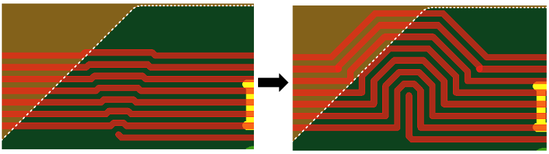 |
| Tidy | When you move the cursor, tracks are pushed away by generating
breaks in segments, if necessary. They are moved in the optimum
way, which minimizes the number of corners that are added. Tracks
can be pushed over obstacles.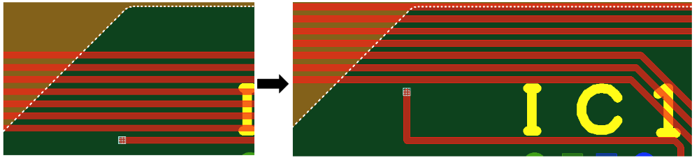 |
45-degree, 90-degree or Free Routing style
Online DRC must be toggled on to enable this functionality.
| Value | Description |
|---|---|
| No tidy | When you click the canvas, the tracks are pushed directly around
the routing. Segment breaks are added to existing tracks to accommodate
the routing. Tracks cannot be pushed over obstacles.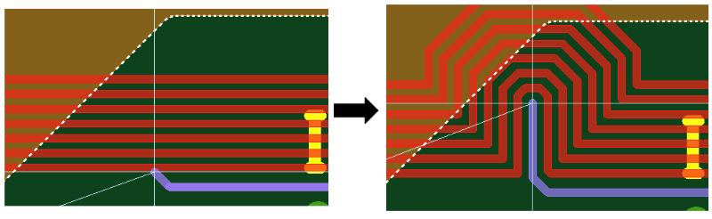 |
| Tidy | When you click the canvas,the tracks are pushed away without
generating segment breaks. Tracks cannot be pushed over obstacles.
 |
When Routing a Trunk
When routing a trunk, the Push aside mode behavior is as follows, regardless of the specified Routing style.
When attempting to add vias though an invisible layer: if Automatic repour is selected for a copper flooded template, then note the following.
- Vias cannot be added when trunk routing, or routing in Activ-45 mode.
- Vias can be added when routing using the 45-degree, 90-degree or Free modes.
| Value | Description |
|---|---|
| No tidy | When you move the cursor, tracks are pushed around the trunk.
Segment breaks are added to existing tracks to accommodate the
trunk. Tracks cannot be pushed over obstacles.
 |
| Tidy | When you move the cursor, tracks are pushed away without generating
segment breaks. Tracks cannot be pushed over obstacles.
 |
Lengthening parameters
| Value | Description |
|---|---|
| Settings | Displays the Design Settings
dialog, Lengthen section. This
allows you to specify the settings that are used by the Lengthen command. The specified settings
are overridden by the settings in the Lengthening
tab, in the Constraint
Browser: Signals section, Signals tab or Constraint
Browser: Signals section, Classes/Groups tab for a selected
E-Net or E-Net class. If Re-lengthen at the end of interactive operations is selected in the Design Settings dialog, Lengthen section, then the following are re-lengthened to meet any length constraints. When the routing or re-routing of a signal is completed:
Note If any pushed signals move back to their original position, then any lengthening blocks on the signals are restored. |
Single Trace (common)
Track width
| Value | Description | |
|---|---|---|
| Fix track width button | Allows you to fix the track width so that all subsequent tracks that you add using this dialog have the value that you specify. If you select a value in the Track width box, then this button is automatically toggled on. | |
| Selected: | If this button is toggled on, then the track width is fixed
to the value that you specify in the Track
width box. Subsequent tracks that you add using this dialog
use this value. The  icon is displayed. If
you specify a value in the Track width
box, then the Fix track width button
is automatically toggled on. icon is displayed. If
you specify a value in the Track width
box, then the Fix track width button
is automatically toggled on. | |
| Not Selected: | If this button is toggled off, then the default track width
is used for all new tracks that you add. This value is specified
in the Rule Editor
Dialog: Tracks Tab. However, if you continue routing an existing
track, then the track width of the relevant track is used.
This is described in more detail in the following note.
The  icon is displayed. icon is displayed. | |
| Track width box | Allows you to set the width of a new track, or the width of a new portion of an existing track that you continue to route. The specified value is used rather than the default track width. If you set a value, then the Fix track width button is automatically toggled on, and the specified value is used for subsequent tracks. The value is saved in the Track width box. Enter a real number greater than 0. |
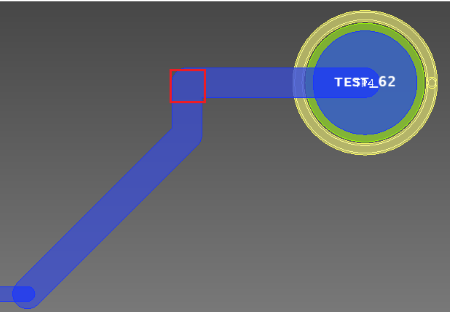
If you continue to route an existing track by adding a new portion to it, then the width of the new portion is inherited from the existing track that you select. The Fix track width button must be toggled off, to make this functionality available. To continue routing a narrow track, to join a wider track, click on the narrow track in the position shown below.
To continue routing a wide track, to join a narrower track, click on the wide track in the position shown below.
If you click on the unrouted net between the two tracks, then the width of the new portion of track is inherited from the closest track to the position that you click. This is illustrated below.
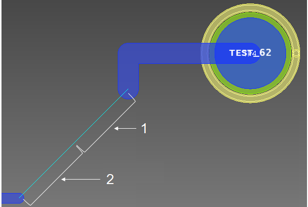
1: Click here to create a wide track.
2: Click here to create a narrow track.
Padstack name
Allows you to select the default padstack, or specify a padstack by selecting it from this box. The padstacks that are listed are specified in the Available padstacks box, in the in the Rule Editor Dialog: Vias Tab.
| Value | Description |
|---|---|
| Default Padstack | Selects the default padstack that is specified in the Rule Editor Dialog, Vias tab. |
| [Padstack name] | The padstack with the specified name is added. |
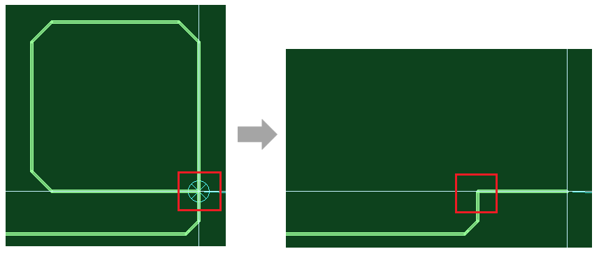
Ring removal
| Value | Description |
|---|---|
| ON | When routing tracks, tracks are automatically removed in order to avoid a loop being created between component pins. Note
|
| OFF | When routing tracks, loops are permitted between component pins. This allows you to manually remove them, if necessary. |
Single Trace (non Activ-45)
Via Spiral
| Value | Description |
|---|---|
| ON | If selected, via spirals are automatically created, when required. |
| OFF | If selected, via spirals are not automatically created. However, you can create them manually. |
| Settings | Allows you to configure spiral vias in the Design Settings dialog. |
Check From-To of layer span
| Value | Description |
|---|---|
| ON | If selected, then the From-To values for via spirals are limited to those shown in the Via layer span section of the Rule Editor dialog, Vias Tab. |
| OFF | If selected, then the From-To values for via spirals are not limited to those shown in the Via layer span section of the Rule Editor dialog, Vias Tab. |
Tangent arc
| Value | Description |
|---|---|
| ON | A tangent arc with the radius specified in Radius of tangent arc is generated at the corner of a track. |
| OFF | The vertex is placed at the corner of a track. |
Radius of tangent arc
| Value | Description |
|---|---|
| Real number greater than 0. | Set the radius of tangent arcs generated when Tangent arc is set to ON. |
Teardrop
| Value | Description |
|---|---|
| ON | Enables the insertion of teardrops at joints with pins or vias, or at track width changes. |
| OFF | Disables the insertion of teardrops. |
| Settings | Allows you to configure teardrops in the Design Settings dialog. |
Antenna removal
| Value | Description |
|---|---|
| ON | Single ended Antenna tracks are removed. |
| OFF | Antenna tracks are not removed. |
Route to end
If 45-degree, 90-degree or Free is selected in the Routing style box, then this section allows you to display a suggested route on the canvas for a track. If Route to End is set to ON, then you can complete a routing pattern by clicking on the target destination, clicking the Spacebar or selecting Finish on the assist menu.
| Value | Description |
|---|---|
| ON | For a selected track, a suggested route is displayed as a dotted
line on the canvas. This is illustrated below for the 45-degree
routing style.
The suggested route for the 90-degree routing style is displayed below.
|
| OFF | A suggested route is not displayed on the canvas for a selected track. |
Shield control
| Value | Description |
|---|---|
| ON | A shield pattern is generated. |
| OFF | No shield patterns are generated. |
| Settings | Allows you to configure shield control in the Design Settings dialog. |
Jumper part name
| Value | Description | |
|---|---|---|
| String | Specify the part name of the jumper to be generated. Specify
jumpers that satisfy the following conditions:
|
Prefix
| Value | Description |
|---|---|
| String | Set the alphanumeric prefix for the reference of the component to be generated. References are created by appending the Start suffix value to this value. |
Start suffix
| Value | Description |
|---|---|
| String | Set the start number for the references of components to be generated. References are created by appending this value to the Prefix value. |
Placement side
Specify the placement side of the component to be generated.
| Value | Description |
|---|---|
| Side A | Components are placed on side A. |
| Side B | Components are placed on side B. |
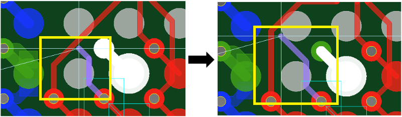
When routing a trace, press and hold Ctrl+Alt to display its entire connection.
Trunking
Via pattern style
| Value | Description |
|---|---|
| Box | Vias are placed in positions where they do not overlap each
other. |
| Inline | Vias are placed in series. |
| Sawtooth | Vias are placed in a zigzag pattern. |
| Forward diagonal | Vias are placed in an upward diagonal line. |
| Backward diagonal | Vias are placed in a downward diagonal line. |
Differential Pair end routing
Allows you to set parameters for the end routing of differential pairs.
| Value | Description |
|---|---|
| ON | When routing differential pairs, the end routing of the signals within the differential pair is done automatically. |
| OFF | When routing differential pairs, the end routing of the signals within the differential pair is not done. |
Dynamic ends only
| Value | Description |
|---|---|
| ON | Only the portion from the route being added to the pin ahead is automatically terminated. |
| OFF | The portion from the route being added to the pin ahead is automatically terminated. If the route has more portions that are not terminated, then those portions are also automatically terminated. |
Distance from target
| Value | Description |
|---|---|
| Large | When the cursor is a long distance from the target pins, the trunk attempts to connect to them. |
| Medium | When the cursor is a medium distance from the target pins, the trunk attempts to connect to them. |
| Small | When the cursor is a short distance from the target pins, the trunk attempts to connect to them. |
Bus end routing
Allows you to set parameters for the end routing of busses. Busses comprise over two signals.
| Value | Description |
|---|---|
| ON | When routing busses, the end routing of the signals within the bus is done automatically. |
| OFF | When routing busses, the end routing of the signals within the bus is not done. |
Dynamic ends only
| Value | Description |
|---|---|
| ON | Only the portion from the route being added to the pin ahead is automatically terminated. |
| OFF | The portion from the route being added to the pin ahead is automatically terminated. If the route has more portions that are not terminated, then those portions are also automatically terminated. |
Distance from target
| Value | Description |
|---|---|
| Large | When the cursor is a long distance from the target pins, the trunk attempts to connect to them. |
| Medium | When the cursor is a medium distance from the target pins, the trunk attempts to connect to them. |
| Small | When the cursor is a short distance from the target pins, the trunk attempts to connect to them. |
Advanced
| Value | Description |
|---|---|
| Settings | Allows you to specify advanced routing settings in the Design Settings dialog, Trunking (Advanced) section. |
