
In a High Speed environment, the Topology Template Manager dialog allows you to configure topology templates, and create new ones that are based on predefined topology templates. The topology templates that you create can be assigned to the E-Nets in the design using the Assign Topology Template dialog. They are not made available in other designs. When you assign a topology template, it is checked automatically in Constraint Browser. If the topological structure of the relevant signal does not follow the assigned topology template, then the assigned value is shown in red in the Topology Template column.
Launch the Topology Template Manager
dialog from the toolbar in Constraint Browser
by clicking  , or by selecting
Edit > Topology Template Manager. Alternatively,
right-click a topology template in the Assign
Topology Template dialog, Topology Template
table, and select Topology Template Manager
on the assist menu.
, or by selecting
Edit > Topology Template Manager. Alternatively,
right-click a topology template in the Assign
Topology Template dialog, Topology Template
table, and select Topology Template Manager
on the assist menu.
If you modify a topology template that is already assigned to E-Nets or differential pairs, then any local pin pair constraint values that are set on them may be changed, without warning, when the topology is reapplied. The following recommendations are provided.
- Add any constraints for E-Nets or differential pairs to the relevant topology template, rather than doing this locally in Constraint Browser.
- When modifying a topology, make a copy of it first. This can then be applied to the relevant nets. This allows you to identify any changes to pin pair constraint information. These changes could be reversed, if necessary, by using the original topology template.
- Set the environment to High Speed by selecting High Speed in the Product Settings dialog, License Settings section, when a High Speed license is available. The High Speed icon on the status bar is displayed in green.
- Other areas of eCADSTAR are not accessible when the Topology Template Manager dialog is launched.
Topology Template
Displays the topology templates that you create in the
design using the Create
Topology Template dialog. These are based on the predefined topology
templates that are provided in eCADSTAR.
Launch the Create Topology
Template dialog by clicking  in this section.
| Value | Description | |
|---|---|---|
|
button |
Launches the Create Topology Template dialog. This allows you to create a topology template that is based on a predefined one that is supplied in eCADSTAR. You can specify the number of inputs and define its name in this dialog. | |
| Topology template table | Displays the topology templates that you create in the Create Topology Template dialog. Click an item to display it in the Tile Editor and Attributes table. In the Tile Editor, you can modify a selected topology template by deleting its components and transmission lines. The Attributes table allows you to specify attributes for each portion of the topology. |
Assist menu
The following commands are displayed on the assist menu by right-clicking an item in the Topology template table.
| Value | Description |
|---|---|
| Delete | Deletes the item that you right-click in the Topology template table. Alternatively, select an item in the Topology template table and press Delete on the keyboard. You cannot undo this command. You can delete multiple topology templates by selecting them using the Ctrl or Shift key, or by dragging the cursor. |
| Rename | Allows you to rename the item that you right-click in the Topology template table. Alternatively, select an item in the Topology template table and press F2 on the keyboard. You can also double-click an item to rename it. |
| Copy | Allows you to copy the item that you right-click in the Topology template table. The copied item is added to the bottom of the Topology template table. The "-copy[n]" suffix is added to it. |
Toolbox
The Toolbox shows the tiles that can be added to the Tile Editor. A different selection of tiles is provided, depending on whether you add a single-ended or differential topology template.
- To place a single instance of a tile, drag it from the Toolbox to the required location in the Tile Editor.
- To place multiple instances of a tile, click the required tile and then click a cell in the Tile Editor to place it. You can continue to place the tile in multiple locations until you press the Esc key.
Single-ended topology template
The following tiles are displayed if you add a single-ended topology template using the Create Topology Template dialog. The icons are shown below for both single-ended and differential topology templates.
| Value | Description |
|---|---|


|
Receiver |

|
Transmission Line |


|
Horizontal connection |


|
Vertical connection |


|
Top to Right connection |


|
Left to Bottom connection |


|
Left to Top connection |


|
Bottom to Right connection |


|
Horizontal to Top Junction |


|
Horizontal to Bottom Junction |


|
Vertical to Right Junction |


|
Vertical to Left Junction |


|
Four way Junction |


|
Resistor |


|
Capacitor |


|
N-port |


|
Resistor termination |


|
N-port termination |
Differential topology template
The following tiles are displayed if you add a differential topology template using the Create Topology Template dialog. The icons are shown below for both single-ended and differential topology templates.
| Value | Description |
|---|---|
|
|
Receiver |
|
|
Transmission Line |
|
|
Horizontal connection |
|
|
Vertical connection |
|
|
Top to Right connection |
|
|
Left to Bottom connection |
|
|
Left to Top connection |
|
|
Bottom to Right connection |
|
|
Horizontal to Top Junction |
|
|
Horizontal to Bottom Junction |
|
|
Vertical to Right Junction |
|
|
Vertical to Left Junction |
|
|
Four way Junction |
|
|
Resistor |
|
|
Capacitor |
|
|
N-port |
|
|
Resistor termination |
|
|
N-port termination |

|
Bridge resistor |

|
Bridge capacitor |

|
Series Resistor termination |

|
Series Resistor Capacitor termination |
Tile Editor
The Tile Editor allows you to configure a selected topology template. You can add tiles from the Toolbox, and move them using the Copy and Paste commands. You can also drag tiles to the required location using the mouse. Topology connections must flow from left to right.
| Value | Description | |
|---|---|---|

|
Zooms in the display of the Tile Editor for all loaded topology templates. Alternatively, press the Ctrl key and scroll the mouse wheel forwards. | |

|
Zooms out the display of the Tile Editor for all loaded topology templates. Alternatively, press the Ctrl key and scroll the mouse wheel backwards. | |

|
Resets the Tile Editor to the default zoom setting for all loaded topology templates. | |
| Tile Editor |
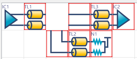
Displays the topology template that you select in the Topology template table. The attributes associated with it are displayed in the Attributes table, below. If you click a cell in the Attributes table, then the relevant portion of the topology template is indicated in the Tile Editor by highlighting it intermittently. You can select tiles using the arrow keys on the keyboard, or by clicking them. You can delete a tile in the Tile Editor by selecting it and pressing Delete on the keyboard. Alternatively, select Delete on the assist menu. The Attributes table is automatically updated to show the changes in the topology template. If there is no longer a compete connection path from the driver, as a result of configuring a topology, then any effected tiles are highlighted in red. This is illustrated below.
Note
|
Assist menu
The following commands are displayed on the assist menu by right-clicking an item in the Tile Editor.
| Value | Description |
|---|---|
| Undo | Reverses the effects of the Delete command in the Tile Editor. Alternatively, press Ctrl+Z on the keyboard. |
| Redo | The Delete command for which the Undo command was applied, is executed again in the Tile Editor. Alternatively, press Ctrl+Y on the keyboard. |
| Create Pin Pair | Creates a pin pair in the Create Pin Pair dialog using the nodes that you select in the Tile Editor. The new pin pair is added to the Attributes table. This command is only made available if you launch the Create Pin Pair dialog by selecting it on the assist menu in the Attributes table. |
| Reset | Removes the values in the Create Pin Pair dialog. If you attempt to create a pin pair that already exists, then clicking Reset allows you to select different pins for it. This command is only made available if you launch the Create Pin Pair dialog by selecting it on the assist menu in the Attributes table. |
| Cut |
Removes a selected tile from the topology and copies it to the clipboard. You can also drag a tile to the required position in the Tile Editor. Alternatively, press Ctrl+X on the keyboard. Note
You cannot cut or delete a driver tile. |
| Copy | Copies a selected tile to the clipboard. Alternatively, press Ctrl+C on the keyboard. |
| Paste | The tile that you copy to the clipboard using the Cut
or Copy command is pasted
to the selected position. You can paste a tile multiple times,
in different positions. Alternatively, press Ctrl+V on the keyboard.
Note You cannot paste an item on a driver tile. |
| Insert | Allows you to insert an empty row above or below a selected tile, or insert an empty column to the left or right. Select the relevant command on the submenu. |
| Delete | Deletes a selected item, or empty row or column. If an item
is not selected or if a selected row or column is not empty, then
this command is made unavailable. Select the relevant command
on the submenu.
Note You cannot cut or delete a driver tile. |
Attributes Table
Allows you to configure the constraint values that are associated with the pin pairs in the topology. Click a cell in the Attributes table to highlight the relevant portion of the topology in the Tile Editor.
- New pin pairs that are created by editing a topology have no constraint values
- If you edit a topology, then the constraint values are removed for all affected pin pairs.
| Item | Description | |
|---|---|---|
| Topology template | Displays the topology template that you select in the Topology template box. | |
| Object | For the topology template that you select in the Topology template box, the pin pairs are displayed for which you can specify attributes. Click an object to show the relevant portion of the topology in the Tile Editor. | |
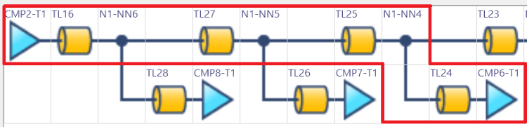
| Transmission Lines | The transmission lines are displayed that are associated with
each pin pair in the Object column.
For example, if the row is selected for the CMP2-T1-CMP6-T1 pin
pair, then the transmission lines TL16, TL24, TL25 and TL27 are
shown in this column. They are also highlighted in the Tile
Editor. This is illustrated below.
 |
|
| Pin Pair Length | For a pin pair that you select in the Object column, this section allows you to specify minimum and maximum values for its length. If the topology template is assigned to a differential pair or E-Net, then the specified values are added to the Min. and Max. columns in the High Speed Routing tab, Pin Pair Length section, in the Constraint Browser: Signals section, Signals Tab, for the relevant pin pair. Click Apply in the Topology Template Manager dialog to update these values. | |
| Min. | Specify the minimum distance between the pins of the pin pair. Enter a value that is greater than 0, and less than or equal to 20000. | |
| Max. | Specify the maximum distance between the pins of the pin pair. Specify a value that is greater than 0, and less than or equal to 20000. | |
| Pin Pair Delay | For a pin pair that you select in the Object column, this section allows you to specify the minimum and maximum delay that is permitted between the relevant pins. If the topology template is assigned to a differential pair or E-Net, then the specified values are added to the Min. and Max. columns in the High Speed Routing tab, Pin Pair Delay section, in the Constraint Browser: Signals section, Signals Tab, for the relevant pin pair. Click Apply in the Topology Template Manager dialog to update these values. | |
| Min. | Specify the minimum delay that is permitted between the pins of the selected pin pair. | |
| Max. | Specify the maximum delay that is permitted between the pins of the selected pin pair. | |
| Track Width | For the pin pairs that you select in the Object column, this section allows you to specify a rule stack that you create in the rule library. | |
| Track Width Stack | Specify a track width stack from the rule library for the pin pair. These are created in the Tracks tab in the Rule Editor Dialog: Tracks Tab dialog. Select a value in the displayed Track Width Stack dialog. | |
| Differential Pair Rule Stack |
Specify a differential pair rule stack from the rule library for the pin pair. These are created in the Rule Editor Dialog: Differential Pairs Tab. This column is only made available if a differential signal is selected in the Topology template box. Note
The following should be considered when routing a differential pair that has a topology template assigned. In the Signals Tree, if you right-click the top level of the differential pair, and click Send Selection on the assist menu, then the entire differential pair is selected and displayed on the canvas. This allows you to start routing it using the Add Route command. However, when selecting a differential pair at this level, an incorrect Differential Pair Rule Stack may be applied to the transmission line which you start routing. This can create width and clearance errors in the routed tracks. To ensure that correct Differential Pair Rule Stacks are applied to each transmission line, follow one of these procedures.
|
|
| Characteristic Impedance | For the pin pairs that you select in the Object column, this section allows you to specify the minimum and maximum characteristic impedance. | |
| Min (Ω) | Specify the minimum characteristic impedance for the pin pair. | |
| Max(Ω) | Specify the maximum characteristic impedance for the pin pair. | |
| Differential Impedance | For the pin pairs that you select in the Object column, this section allows you to specify minimum and maximum values for differential impedance. This column is only made available if a differential signal is selected in the Topology template box. | |
| Min (Ω) | Specify the minimum differential impedance value that is permitted for the pin pair. | |
| Max (Ω) | Specify the maximum differential impedance value that is permitted for the pin pair. |
Assist menu
The following commands are displayed on the assist menu by right-clicking a cell in the Attributes Table.
| Value | Description |
|---|---|
| Create Pin Pair | Allows you to create a pin pair in the displayed Create Pin Pair dialog. In the Tile Editor, select the first and last pins of the pin pair by clicking them. Click Create in the Create Pin Pair dialog to create the pin pair. The new pin pair is added to the Attributes table. |
| Delete Pin Pair | Allows you to delete the pin pair that you select in the Attributes table. Select multiple pin pairs using the Ctrl or Shift key, or by dragging the cursor. |
| Value | Description |
|---|---|
| OK | Saves the changes that you make in the Topology Template Manager dialog, and closes the dialog. Unused cells in the Tile Editor are removed to reduce the size of topology. |
| Cancel | Closes the Topology Template Manager dialog without saving your changes. |
| Apply | Saves the changes that you make in the Topology Template Manager dialog. The dialog remains open. Unused cells in the Tile Editor are removed to reduce the size of topology. |
