
In a High Speed environment, the Assign
Topology Template dialog allows you to assign a topology template
to the E-Net that you select in the Signals
tree, in the Constraint Browser:
Signals section, Signals tab. Launch this dialog by selecting an E-Net,
and then pointing the cursor at the Topology Template
column in the Design
Rule tab. Click the displayed  button to launch the dialog. When the Assign Topology
Template dialog is displayed, other areas of eCADSTAR
remain accessible.
button to launch the dialog. When the Assign Topology
Template dialog is displayed, other areas of eCADSTAR
remain accessible.
To display multiple E-Nets in the Assign
Topology Template dialog, select them in the Signals
tree using the Ctrl or Shift
key, or by dragging the cursor. In the Design
Rule tab, select all columns in the Topology
Template column, and then click the button.
All selected E-Nets are displayed in the 1.
Select signals section.
The assigned topology template is checked automatically in Constraint Browser. If the topological structure of the relevant signal does not follow the assigned topology template, then the assigned value is shown in red in the Topology Template column.
If you modify a topology template that is already assigned to E-Nets or differential pairs, then any local pin pair constraint values that are set on them may be changed, without warning, when the topology is reapplied. The following recommendations are provided.
- Add any constraints for E-Nets or differential pairs to the relevant topology template, rather than doing this locally in Constraint Browser.
- When modifying a topology, make a copy of it first. This can then be applied to the relevant nets. This allows you to identify any changes to pin pair constraint information. These changes could be reversed, if necessary, by using the original topology template.
1. Select signals
Displays the E-Nets that you select in the Constraint Browser: Signals section, Signals tab, and shows the topology templates that are associated with them. An image of the associated topology template and details of its components are displayed by clicking an E-Net in the Signals table.
| Value | Description | |
|---|---|---|
| Filter | Allows you to filter the contents of the Signals table by entering an alphanumeric value. Only the E-Nets in the Signal column are shown that contain the specified value. The values that you enter are saved until you close the relevant design. | |
| Signals table | Displays the signals that you select in the Constraint
Browser: Signals section, Signals tab. If a topology has been
assigned to a signal, then its name and the number of active pins
is shown in this table. If you select a row, then the existing
topology templates are displayed in the Topology
Template table that are compatible with the relevant E-Net.
The top row in the Topology Template
table is automatically selected. The nodes in the selected
topology template are shown in the 3.
Assign components to each node section, and a preview
is shown at the bottom of the dialog. If no compatible topology
template exists in the design for the selected E-Net, then "No
Matching template" is displayed in the 2.
Select a topology template section. Note
|
|
| Signal | Displays the E-Net that you select in the in the Constraint Browser: Signals section, Signals tab. | |
| Topology | If you assign a topology template to an E-Net in this dialog, then it is displayed. If a compatible topology template exists in the design, then you can assign it to a selected E-Net by clicking it in the Topology Template table, and then clicking Apply or OK. | |
| Number of Receivers | Displays the number of receivers. This is the total number of devices, excluding the driver and any passive devices. The active pin for each node in the topology is shown, in brackets, in the Components table, Reference column. |
2. Select a topology template
Allows you to create a new topology template using a predefined one, and associate a topology template with the E-Nets that you select in the 1. Select signals section.
| Value | Description | |
|---|---|---|
| Create Template | Displays the Create Topology Template dialog. This allows you to create a topology template that is based on a predefined one. You can specify the number of inputs and define its name in this dialog. The number of inputs shown is automatically set to match the number of receivers in the selected E-Nets. However, the topology templates that are listed may not be topologically compatible with them. The Topology Template Manager is also launched when you click Create Template. When you close the Create Topology Template dialog, the Topology Template Manager is displayed. This allows you to configure the topology template that you create. When you close the Topology Template Manager dialog, the Assign Topology Template dialog is displayed. If the new topology template is compatible with the E-Nets selected in the 1. Select signals section, then it is displayed in the Topology Template table, in this dialog. | |
| Filter | Allows you to filter the contents of the Topology Template table by entering an alphanumeric value. Topology templates are shown that only contain the specified value. The values that you enter are saved until you close the relevant design. If no compatible topology templates exist in the design, then the Filter box is hidden and "No Matching Templates" is displayed in this section. | |
| Topology Template table | Topology templates are displayed whose topologies are compatible with the E-Nets that you select in the 1. Select signals section. If you select multiple E-Nets, then topology templates are only shown that are compatible with all of them. If no compatible topology templates exist in the design, then this table is hidden and "No Matching Templates" is displayed in this section. | |
| Topology Template |
For the E-Nets that you select in the 1. Select signals section, click a topology template to associate it with them. When you click Apply or OK in this dialog, it is assigned to the E-Nets. The pin pairs for the relevant E-Nets, based on the specified topology template, are added to the Signals tree, in the Constraint Browser: Signals section, Signals tab. These are displayed in the Pin Pairs folder. If this folder does not exist in the Signals tree for the relevant E-Net, then it is created automatically. If you click a topology template, then an image and details of its components are displayed in the Preview and 3. Assign components to each node sections, respectively. Note
To edit the topology templates in a design and assign values to them, right-click in this column, and select Topology Template Manager on the assist menu. The Topology Template Manager is displayed. |
3. Assign components to each node
This section allows you to specify the components that are associated with each node in the selected topology template. This ensures that the specified topology matches the topology of the E-Net.
| Value | Description | |
|---|---|---|
| Components table |
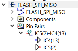
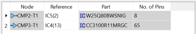
For the E-Nets selected in the 1. Select signals section, if compatible topology templates exist in the design, then the associated details are displayed in this section. This includes the nodes, reference designators, parts and the number of pins on each part. The order in which the nodes are listed in this table should reflect the order in which the relevant pins are connected in the E-Net. This is illustrated in the following example. This shows an E-Net that joins pin 2 on IC5 to pin 13 on IC4. The driver pin, IC5(2), is indicated by a red circle. The receiver pin, IC4(13), is indicated by a blue circle.
In the Components table, the driver pin is set by selecting IC5(2) in the first row. The receiver pin is set by selecting IC4(13) in the second row.
Specify a component for each row by clicking in the Reference column, and selecting it from the displayed list. |
|
| Node |
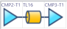
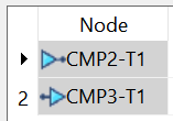
Displays the nodes in the topology template that you select in this dialog. These are listed in the Components table in the order that is specified by the topology template. For example, the CMP2-T1 and CMP3-T1 nodes shown below are specified as the driver pin and receiver pin, respectively, by the topology template. This is due to the order in which they are connected in the topology template.
In the Node column, the driver pin, CMP2-T1, appears in the first row. The receiver pin, CMP3-T1, appears in the second row.
|
|
| Reference | Specify the component that is associated with each node in
the selected topology template by clicking in the Reference
column for the relevant row, and selecting it from the displayed
list. This ensures that the specified topology matches the topology
of the E-Net. The order in which the nodes are listed in this
table should reflect the order in which the pins are connected
in the E-Net. This is shown for the relevant E-Net in the Signals tree, in the Constraint
Browser: Signals section, Signals tab.
Note If you change the order in which the pins are connected in a topology template, it is recommended that you delete the existing Pin Pairs folder before you click Apply. This is located in the Signals tree in the Constraint Browser: Signals section, Signals tab. |
|
| Part | The part associated with the component that you select in the Reference column. | |
| No. of Pins | The number of pins on the part that is shown in the Part column. |
Preview pane
| Value | Description |
|---|---|
| Preview box | Displays the topology template that you select in the Topology Template table in the 2. Select a topology template section. You cannot edit the displayed image. To edit it, right-click the relevant row in the in the Topology Template table, and select Topology Template Manager. The Topology Template Manager dialog is displayed. |
| Value | Description |
|---|---|
| OK | Saves the settings that you specify in this dialog, and closes it. If you select a topology template in the Topology Template table, then it is assigned to the E-Nets that are selected in the 1. Select signals section. The pin pairs for the relevant E-Nets, based on the specified topology template, are added to the Signals tree, in the Constraint Browser: Signals section, Signals tab. These are displayed in the Pin Pairs folder. If this folder does not exist in the Signals tree for the relevant E-Net, then it is created automatically. |
| Cancel | Closes this dialog without saving any changes that you make. |
| Apply | Saves the settings that you specify in this dialog. If you select a topology template in the Topology Template table, then it is assigned to the E-Nets that are selected in the 1. Select signals section. The pin pairs for the relevant E-Nets, based on the specified topology template, are added to the Signals tree, in the Constraint Browser: Signals section, Signals tab. These are displayed in the Pin Pairs folder. If this folder does not exist in the Signals tree for the relevant E-Net, then it is created automatically. |
