Area Fill (Polygon)
The Area Fill (Polygon)
command allows you to create a polygonal area fill, height limit area,
rule area or component group on the canvas. It is displayed by clicking
, or
on
the ribbon in eCADSTAR PCB Editor.
It is only available in 2D View mode.
Select an option in the top of this dialog to specify relevant settings
for the selected option. The following options can be selected.
Note
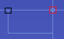
If a closed shape can be created from the current position of the cursor, then a circular mark is displayed on the canvas. This takes account of the
Angle lock value. Click this mark to create a point on the area fill. If
Angle lock is set to
Free, then the circular mark is displayed at angles from the start position which are multiples of 45 degrees. This is illustrated below for the angle of 90 degrees. The start position is highlighted in black.
| Item |
Description |
| Copper
|
If a conductor layer is set as the Active
Layer, then selecting this option allows you to specify a
copper area fill for it. If a non-conductor layer is set as the
Active
Layer, then this option is made unavailable. You can create
a template area by selecting ON in
the Template area field. Before
you define the template area, you must specify an object on the
canvas that has a net.
Warning
If no signal is selected when creating
a copper area fill, then the copper shapes that are created are
added to the No net net. Consequently, they are connected to all other
copper items on this net, including pads, pins and copper areas.
Shorting all unconnected items together in this way may be particularly
problematic if aNo netpin
is internally connected within a component. |
| Figure
|
If a non conductor layer is set as the Active
Layer, then selecting this option allows you to specify an
area fill for it. If a conductor layer is set as the Active
Layer, then this option is made unavailable. |
| Height limit
|
For a design that has height limit area layers, this option
allows you to create a height limit area. See: Creating
a Height Limit Area. |
| Rule
|
Allows you to create a rule area. The rules that you specify
for a rule area override the routing rules in the associated technology.
See: Creating
a Rule Area. |
| Component Group
|
Allows you to create a component group on the canvas. Before
doing this, you must create a component group using the Component
Group Settings dialog. The component groups that you create
can be selected in the Name box, in
this dialog. After you add component groups to the canvas, add
the associated components by selecting the relevant component
group in the Grouped components
section of the Arrange Components
dialog. Alternatively, click the Component
Group option and draw an area on the canvas that includes
the components associated with the relevant component group. |
Copper
Refer to the Warning message
above before selecting this option.
Angle lock
| Value |
Description |
| 45-degree
|
The angle between the sides of the figure to be input is limited
to 0, 45, 90, 135, 180, 225, 270 and 315 degrees. |
| 90-degree
|
The angle between the sides of the figure to be input is limited
to 0, 90, 180 and 270 degrees. |
| Free |
The angle between the sides of the figure to be input is not
locked. |
Tangent arc
| Value | Description |
|---|
| ON | A tangent arc with the radius specified in Radius of tangent
arc is generated at the corner of a figure. |
| OFF | The vertex is placed at the corner of a figure. |
Radius of tangent arc
| Value | Description |
|---|
| Real number greater than 0. | Set the radius of tangent arc to be generated. |
Template area
| Value | Description |
|---|
| ON | If Copper is selected in
this dialog, then a template area is created on the canvas. Before
you define the template area, you must specify an object on the
canvas that has a net. This field is made available only if Copper is selected.
Note- When adding a template area to a rule area
on the canvas: if the Minimum copper
width is defined by Track width stack check box is selected
in the PCB
Editor: Application Settings, Area
fill section, then the track width is ignored that is set
for the rule area. The track width stack is applied that you specify
in the Default track width stack
box in the Rule
Editor Dialog: Tracks Tab. However, this value is overridden
by any values specified for the relevant net in the Design
Rule tab, Track Width Stack
column in the Constraint
Browser: Signals section, Signals Tab or Constraint
Browser: Signals section, Classes/Groups tab.
- To assign mesh parameters to template copper, select the template area on the canvas, and then specify values in the Mesh Parameters dialog. This is displayed by clicking on the ribbon, and then clicking Settings in the Generate Mesh dialog. Alternatively, right-click a template area on the canvas and select on the assist menu.
WarningIf a template area is changed to a mesh, then it is not affected by the following commands. If a template area is changed to a mesh, then deleting the contents of the mesh reverts it to a template area. |
| OFF | A template area is not created on the canvas. |
Pen width
| Value | Description |
|---|
| Real number equal to or greater than 0. | Set the pen width of the area fill to be generated. |
Thermal relief
| Value | | Description |
|---|
| ON | | In the same net as the area fill to be generated: the subtract
process is executed on pins, vias, and padstacks in components.
This generates thermal lines. |
| OFF | | In the same net as the area fill to be generated: the subtract
process is not executed on pins, vias, and padstacks in components. |
| | Settings | Displays the Design
Settings dialog. This allows you to set the thermal relief
values which are shared between multiple commands. |
Subtract parameter
| Value | Description |
|---|
| Settings | Displays the Design
Settings dialog. This allows you to set the Subtract
parameter values which are shared between multiple commands. |
Figure
Angle lock
| Value | Description |
|---|
| 45-degree | The angle between the sides of the figure to be input is limited
to 0, 45, 90, 135, 180, 225, 270 and 315 degrees. |
| 90-degree | The angle between the sides of the figure to be input is limited
to 0, 90, 180 and 270 degrees. |
| Free | The angle between the sides of the figure to be input is not
locked. |
Tangent arc
| Value | Description |
|---|
| ON | A tangent arc with the radius specified in Radius of tangent
arc is generated at the corner of a figure. |
| OFF | The vertex is placed at the corner of a figure. |
Radius of tangent arc
| Value | Description |
|---|
| Real number greater than 0. | Set the radius of tangent arc to be generated. |
Pen width
| Value | Description |
|---|
| Real number equal to or greater than 0. | Set the pen width of the area fill to be generated. |
NoteIf you create an area fill on a user-defined keepout layer using the
Figure option, then you can select whether nets or area fills are allowed within the area fill. In the
Properties Panel
,
Net keepout settings
row, click

in the
Value
column. The
Net Keepout Settings dialog
is displayed. Select
Line allowed or
Area fill allowed in the
Allow line/area fill box.
Height limit
| Value | Description |
|---|
| 45-degree | The angle between the sides of the figure to be input is limited
to 0, 45, 90, 135, 180, 225, 270 and 315 degrees. |
| 90-degree | The angle between the sides of the figure to be input is limited
to 0, 90, 180, and 270 degrees. |
| Free | The angle between the sides of the figure to be input is not
locked. |
Tangent arc
| Value | Description |
|---|
| ON | A tangent arc with the radius specified in Radius of tangent
arc is generated at the corner of a figure. |
| OFF | The vertex is placed at the corner of a figure. |
Radius of tangent arc
| Value | Description |
|---|
| Real number greater than 0. | Set the radius of tangent arc to be generated. |
Height
| Value | Description |
|---|
| Real number equal to or greater than 0. | Specify the limit value for height limit areas. |
Layer name
| Value | Description |
|---|
| Layer name | Lists the Height Limit Area layers in the design. Select the
layer on which height limit areas are added. |
Rule
Angle lock
| Value | Description |
|---|
| 45-degree | The angle between the sides of the figure to be added is limited
to 0, 45, 90, 135, 180, 225, 270 and 315 degrees. |
| 90-degree | The angle between the sides of the figure to be added is limited
to 0, 90, 180 and 270 degrees. |
| Free | The angle between the sides of the figure to be added is not
locked. |
Tangent arc
| Value | Description |
|---|
| ON | A tangent arc with the radius specified in Radius
of tangent arc is generated at the corner of a figure. |
| OFF | The vertex is placed at the corner of a figure. |
Radius of tangent arc
| Value | Description |
|---|
| Real number greater than 0. | Set the radius of tangent arc to be generated. |
Rule area attributes
| Value | Description |
|---|
| Detail | Displays the Rule
Area Attributes dialog. This allows you to specify the details
of the rule area. |
Component Group
Angle lock
| Value | Description |
|---|
| The angle between the sides of the area to be created is limited
to 0, 45, 90, 135, 180, 225, 270 and 315 degrees. |
| 90-degree | The angle between the sides of the figure to be input is limited
to 0, 90, 180, and 270 degrees. |
| The angle between the sides of the area to be created is not
locked. |
Tangent arc
| Value | Description |
|---|
| ON | A tangent arc with the radius specified in Radius
of tangent arc is generated at the corner of a figure. |
| OFF | The vertex is placed at the corner of a figure. |
Radius of tangent arc
| Value | Description |
|---|
| Real number greater than 0 | Set the radius of tangent arc to be generated. |
Name
| Value | Description |
|---|
| String | Select the name of the target component group. This is specified
in the Component Group Settings
dialog. |
Placement side
| Value | Description |
|---|
| A component group for side A is created. The name "[component
group name](A)" is assigned to it. |
| A component group for side B is created. The name "[component
group name](B)" is assigned to it. |
| A component group for both sides is created. The name "[component group name]" is assigned to it. |
Group settings
| Value | Description |
|---|
| Settings | Displays the Component Group Settings
dialog. This dialog allows you to create component groups, and
add components to them. |
Note- If you select a non-rectangular component
group in the Arrange Components dialog,
then some components may be arranged outside of this area by the Arrange Components command. These components
will need to be placed manually.
- To display the names of component groups
on the canvas, select Component group
on the Canvas View Settings dialog,
Mark Tab.

