The Mesh Parameters dialog allows you to specify meshplane parameters individually for each conductor layer, and collectively for all non-conductor layers. After you set the required parameters, close the dialog and create the mesh using the Generate Mesh dialog. The Mesh Parameters dialog is displayed by clicking Settings in the Generate Mesh dialog .
| Value | Description | |
|---|---|---|
| Layer | Shows each conductor layer in the design, and a layer named
Non Cond Layer.
|
|
| Mesh | Allows you to specify the parameters that are applied to the relevant conductor layer or non-conductor layer in the design. | |
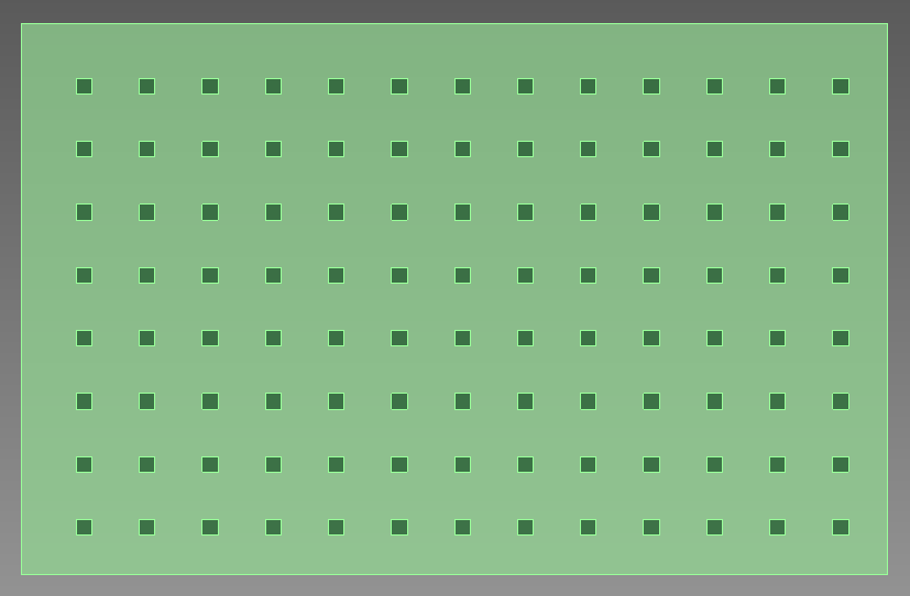
| Type | Specify the shape of the cutout that is used for the mesh.
|
|
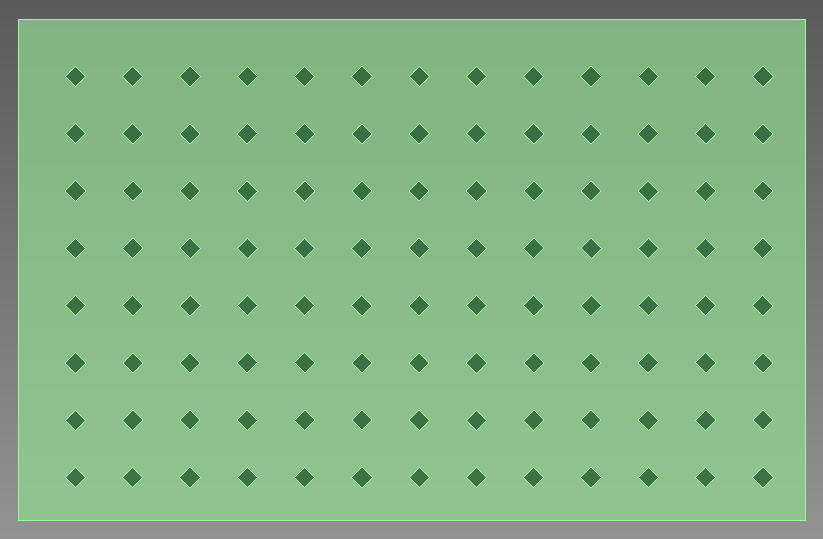
| Angle of shape | Set the angle of the square cutout shapes that are used for
the mesh. Specify a real number equal to or greater than 0, and
smaller than 360.
|
|
| Aperture | Set the size of the cutout shapes that are used for the mesh. Specify a real number equal to or greater than 0. The value in the Spacing column is calculated automatically, based on the combination of values that you specify for Aperture and Pitch. | |
| Pitch | Set the distance between the center points of each cutout shape in the mesh. Specify a real number equal to or greater than 0, and greater than the value of Aperture. The value in the Spacing column is calculated automatically, based on the combination of values that you specify for Pitch and Aperture. | |
| Spacing | Shows the spacing between the rows of cutouts in the mesh. This value is calculated automatically, based on the values that you specify for Aperture and Pitch. An error mark is displayed until you enter a valid combination of values in these fields. A real number is produced that is equal to or greater than 0. | |
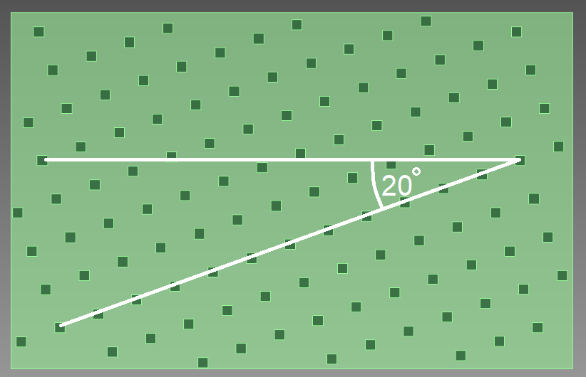
| Angle of sequence | Set the angle of the mesh to be generated. Specify a Real number
equal to or greater than 0, and smaller than 360.
|