
Settings for SPICE Simulation
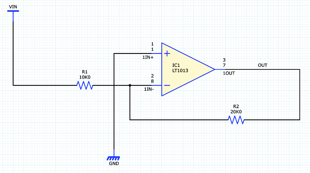
Before performing analog simulation, there are several properties that you must apply to components within the design. This section uses a design which enables analog simulation of the following simple inverting amplifier circuit.
Task 5a: Assigning a SPICE Model Name
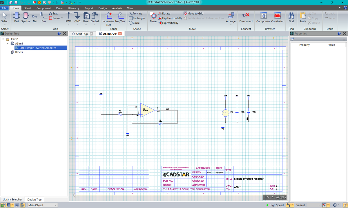
- On the Start menu, click eCADSTAR [Version] > Schematic Editor [Version]. eCADSTAR Schematic Editor is launched.
- In the File tab, click Open. Alternatively, click Open on the Home tab. The Open dialog is displayed.
- Browse to the following location and click Open: C:\Users\Public\eCADSTAR\eCADSTAR [Version]\Analysis\SPICE\ASim1\ASim1.sdes.
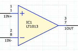
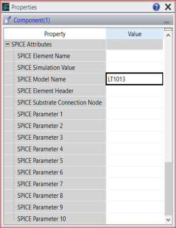
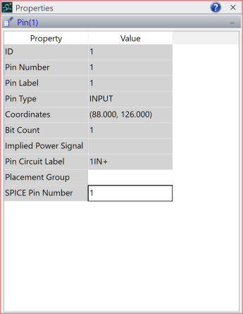
- Select the operational amplifier component IC1, and ensure the Properties panel is displayed.
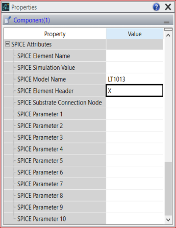
- In the Properties panel, expand the SPICE Attributes property. For the SPICE Model Name property, enter the value "LT1013" as the device model name. This device model is available in the LTC library that was specified in the Applications Settings dialog in a previous task.
The LT1013 device model is a precision operational amplifier, and is used in this inverting amplifier circuit during the training. The datasheet for this component is provided here: https://www.ti.com/document-viewer/LT1013/datasheet.
Task 5b: Setting a SPICE Element Header
Because the reference designator for the operational amplifier component is IC1, this is considered a current source by the SPICE Analog Simulator and correct simulation cannot proceed. A SPICE Element Header can be defined to overcome this.
- Continuing from the previous task, ensure that IC1 is selected and the SPICE properties are displayed in the Properties panel.
- In the Properties panel for the SPICE Element Header property, enter the value "X".
If the SPICE Element Name and SPICE Element Header properites are not populated with a value. The fallback property Reference Designator Prefix on a component is used as a prefix to a reference designator to define a component type within the SPICE netlist.
Task 5c: Assigning SPICE Pin Numbers
To ensure correct pin mapping between the operational amplifier component pins and the SPICE model pins, the property SPICE Pin Number must be set on each functional pin of the component.
- Continuing from the previous task, set the filter to Component Pin on the Status Bar. This enables easier selection of the pins.

- On component IC1, select the pin 1 (1IN+).
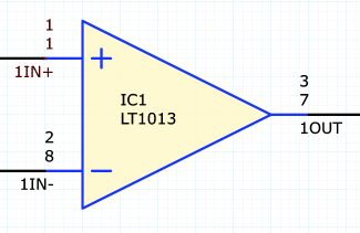
- In the Properties panel, the property SPICE Pin Number must be mapped to the equivalent pin definition in the SPICE model. For component pin 1, enter "1" for the SPICE Pin Number value.
- Continue mapping the component pin numbers to the SPICE model numbers. Use the table below for reference.
The pins for the positive and negative power supplies do not require mapping, as they are defined in the parts library.
| Component Pin Function | Component Pin Number | SPICE Model Number |
|---|---|---|
| Non-Inverting Input | 1 (1IN+) | 1 |
| Inverting Input | 2 (1IN-) | 2 |
| Output | 3 (1OUT) | 5 |
| Positive Supply | 4 (VCC+) | 3 |
| Negative Supply | 5 (VCC-) | 4 |
- All properties are now defined in the schematic design for the SPICE analog simulation.
- Select
 File
> Save Design to save the schematic design.
File
> Save Design to save the schematic design.
Task 5d: Assigning SPICE Element Headers to Voltage Sources
To ensure Voltage Sources are present within the SPICE Netlist the SPICE Element Name property requires a value to be added to identify them to the LTspice application.
- Continuing from the previous task, set the filter to Main Object on the Status Bar.
- On the canvas locate and select the Voltage Source symbol named VIN1.
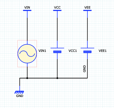
- In the Properties panel, set the property SPICE Element Header to "V". This will represent the symbol as a Voltage Source within the SPICE netlist.
- Repeat setting the SPICE Element Header to "V" for symbols named VCC1 and VEE1.
- All properties are now defined in the schematic design for the SPICE analog simulation.
- Select File
> Save Design to save the schematic design.
Related Topics
SPICE Controller Tools
Component and Pin Properties for SPICE Simulation
