
LTspice Installation and eCADSTAR Configuration
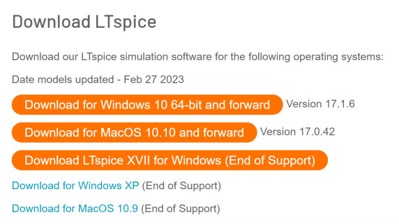
LTspice® is a high-performance SPICE simulation software and waveform viewer, with enhancements and models for easing the simulation of analog circuits. The application is supplied and trademarked by Analog Devices and can be downloaded from the following URL:
https://www.analog.com/en/design-center/design-tools-and-calculators/ltspice-simulator.html
Task 1: Installing LTspice
- Using the above link, download and begin installation of the LTspice application onto your computer. This is the only analog simulator application that eCADSTAR Schematic Editor’s SPICE Controller interfaces with.
- To continue, follow the on-screen instructions of the LTspice installer.
- Extract the LTspice library provided in the installation as follows.
- Open the file lib.zip in the directory C:\Program Files\ADI\LTspice, and extract the contents to a location on your computer. In this training, they have been extracted to the directory C:\Users\Public\eCADSTAR\LTspice.
For the purposes of this training, a 64-bit version of LTspice is installed at the default location: C:\Program Files\LTC\LTspiceXVII. This location is referenced throughout the training.
Analog Simulation Environment Settings
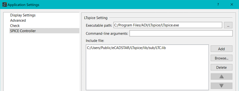
eCADSTAR Schematic Editor must be configured so that the SPICE Controller commands can interface with the LTspice simulator. The Application Settings dialog contains a section called SPICE Controller, where environment settings are specified. These are shown below.
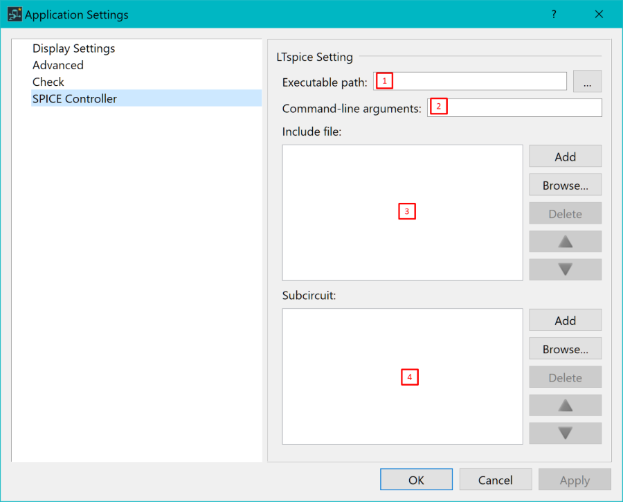
- Executable path: the path to the .exe file for the simulation application. In eCADSTAR, this is the path to the LTspice application.
- Command-line arguments: command-line arguments supported by the LTspice application. A full list of these is provided here: http://ltwiki.org/LTspiceHelp/LTspiceHelp/Command_Line_Switches.htm.
- Include file: text files that can include analysis statements, circuit Nets or device models. If included here, then they are added when the simulation is performed.
- Subcircuit: an output file for the simulation. When you create a hierarchy design in eCADSTAR, you can make lower-hierarchy circuits into device models in subcircuit (.SUBCKT) format.
Task 2: Setting the Executable Path in Application Settings
- On the Start menu, click eCADSTAR [Version] > Schematic Editor [Version]. eCADSTAR Schematic Editor is launched.
- On the File tab, click Configuration > Application Settings. The Application Settings dialog is displayed.
- In the Application Settings dialog, select SPICE Controller.
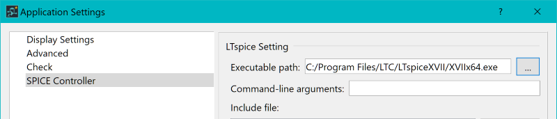
- Using the browse button
 for
the Executable path, set this to the location of the installed LTspice
application. By default this is: C:\Program
Files\LTC\LTspiceXVII\XVIIx64.exe.
for
the Executable path, set this to the location of the installed LTspice
application. By default this is: C:\Program
Files\LTC\LTspiceXVII\XVIIx64.exe. - Click Apply. The change is confirmed, and the dialog remains open.
Task 3: Adding Include Files for the Simulation
- In the Application Settings dialog, click [Browse...] in the Include file section. An open file dialog is displayed.
- Browse to the LTspice installation directory: C:\Program Files\LTC\LTspiceXVII, and select the SPICE model library file LTC.lib. This is in the lib\sub directory.
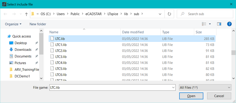
- Click Open to confirm the selection.
- Click Apply in the Application Settings dialog to confirm the setting. The dialog remains open.
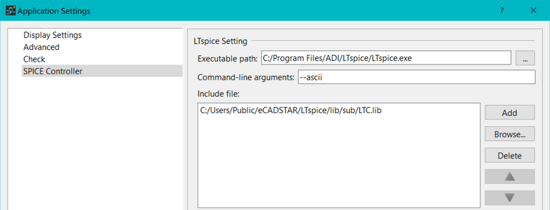
Task 4: Setting Command-Line Arguments
- In the Application Settings dialog, Command-line arguments field, enter the following text: "--ascii". Click Apply to confirm the setting.
The setting of the "--ascii" argument enables LTspice to convert the Operating Point Display results data into ascii format. This enables the data to be back annotated from LTspice to eCADSTAR Schematic Editor.
- Click OK to close the Application Settings dialog.
Related Topics
Component and Pin Properties for SPICE Simulation
Settings for SPICE Simulation
