
Setting Supply Systems
The power required for an IC to operate is supplied by a sophisticated system composed of regulators, capacitors, filters and other various elements. This is called the supply system. It can be divided into the power system and ground system. Each system comprises one or more power and ground that contains area fills, routing, vias and passive components. In this task, you will configure the supply system settings.
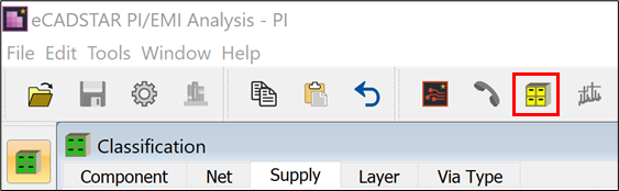
- Select Window > Classification to open the Classification view. Alternatively, press the Ctrl and 1 keys.
- In the Supply tab, check the Power and Ground signals and their associated voltage values.
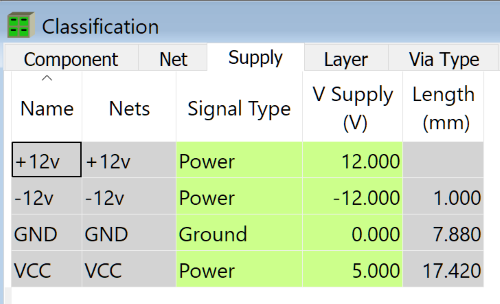
- To form a supply system, connect VCC and SIGN001203. SIGN001203 is classified as a general signal. However, VCC and SIGN001203 are connected via a 0Ω resistor on the layout.
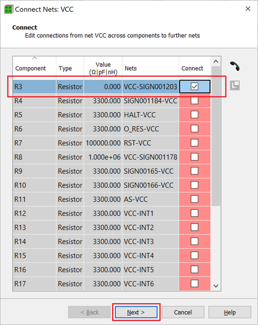
- Right-click on the Signal Type value for VCC, and select Connect Nets on the assist menu. In the Connect Nets dialog, select the Connect check box for R3 and click Next >.
The Connect Nets setting is available only when there are connectable nets. The conditions for connectable nets are shown below.
- Both nets are of the same supply signal type (Power or Ground), and with the same supply voltage.
- Both nets are of the same supply signal type (Power or Ground), and one of the nets has the default supply voltage.
- One of the nets is of the supply signal type (Power or Ground), and the signal type of the other is default or UK (Unknown).
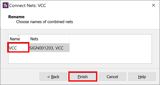
- Select "VCC" in the Name column, and click Finish.
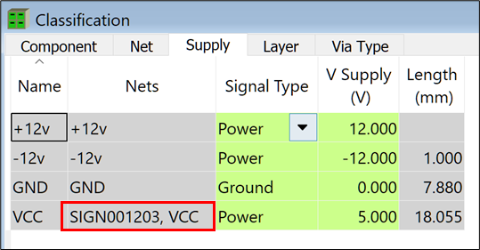
- Confirm that SIGN001203 is now connected to VCC.
- On the toolbar, click
 Classify.
This task is demonstrated in the following video.
