
Introduction to PI Analysis
The PI Analysis module in eCADSTAR models power and ground planes equivalently using the LCR (Inductance, Capacitance, Resistance) grid method. It also analyzes resonance (Impedance) between those planes. This method is used to display an impedance map, which shows the characteristics of power and ground planes (input impedance) when viewed from the pin coordinates of an IC.
This method is different from the experimental method
which is adopted in conventional types of resonance analyses, which analyze
diffusion from a wave source. The new method allows you to check the impact
on ICs, as well as from ICs. It also allows you to simultaneously check
the impact from decoupling capacitors. This is done without setting and
analyzing the wave source for each analysis, according to the noise source.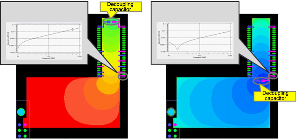
Main features
- Analyzing the input impedances of ICs.
- Displaying the impedance map on the board.
- Analyzing decoupling capacitor characteristics.
Option Settings
This section explains how to check and set analysis conditions for PI analysis.
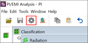
- On the toolbar, click
 Options. The Options
dialog is displayed.
Options. The Options
dialog is displayed.
- Open the Classification tab, and configure the setting highlighted below.
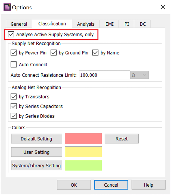
- Selecting the Analyse Active Supply Systems, only check box specifies that only power and ground supply pins are candidates for the measurement of IC pins. These are defined using the simulation library, etc. If the check box is deselected, then other pins that are connected to power and ground nets are also set as candidates for measurement.
- Select the PI tab, and configure the settings highlighted below.
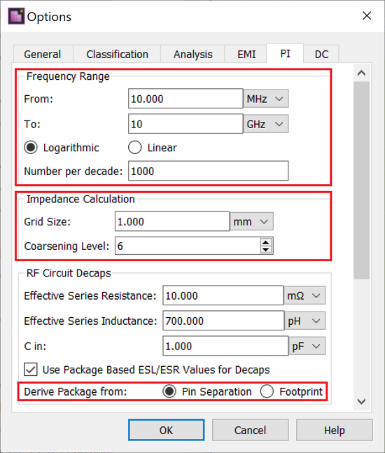
- In the Frequency Range section, specify a minimum frequency of “10 MHz”, and a maximum frequency of “10 GHz”. Set Number per decade to “1000”. One decade is a unit for measuring frequency ratios on a logarithmic scale. One decade corresponds to a ratio of 10, between two frequencies (a difference of an order of magnitude).
- The Impedance Calculation group contains parameters that are used to control analysis meshes. Grid Size defines the minimum mesh size, set “1.0 mm”. Coarsening Level defines the maximum coarseness level of meshes, set to “6”.
- Setting Derive Package from defines the method used to identify the package size for Decaps during analysis.
- Click OK to close the Options dialog.
This task is demonstrated in the following video.
