
The contents of the Hole/Area sub-tab in the Conductor Clearance tab of the Rule Editor dialog are described below. This sub-tab allows you to specify design rule groups that define the minimum clearances between holes and layout areas, and conductor types. The design rule groups can then be assigned to each conductor layer.
| Item | Description | |
|---|---|---|
| Clearance Priority | Allows you to select how the effective value for conductor clearance is set. This can be set by searching a hierarchical list of clearance values. Clearance rules that are set in the Conductor Clearance: Voltage Difference Tab, Constraint Browser or the Default Design Rule Stack section in Rule Editor are followed, in the hierarchical order shown below. Alternatively, you can use the largest clearance value that is specified in either Constraint Browser or Rule Editor. | |
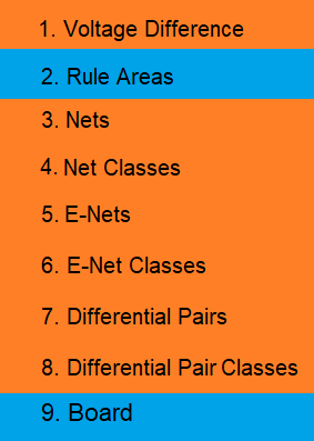
| Use hierarchy | The effective value for conductor clearance is set by checking
clearance rules in the following order. The first clearance value
that is found is used. Click the relevant row in the following
image for a description of where the value is set.
Note
|
|
| Use largest value | The largest clearance value is used that is set in either the
Design
Rule sub-tab, Voltage Difference
Clearance section in Constraint
Browser, or in the Default
design rule stack section in Rule
Editor. In the following example, a clearance of 0.1 mm is
set in the Default
design rule stack, and a clearance formula of 0.00305
* Vdiff + 0.05000 is specified in the Clearance
dialog.
Below approximately 16V, the clearance is defined by the Default design rule stack. Above this voltage, the clearance is defined by the formula as this produces the largest clearance values. |
Default design rule stack
| Item | Description |
|---|---|
| Default design rule stack box | After defining a design rule stack in the Design rule stack section, select the default design rule stack. This defines the minimum clearances for holes and layout areas that are used by default. This is a mandatory setting. |
Design Rule Stack
Define design rule stacks, and design rule groups to the conductor layers associated with each design rule stack. At least one design rule stack must be specified.
| Item | Description |
|---|---|
| Design Rule Stack box | Allows you to define the name of a design rule stack. |
| Add | Define the name of a design rule stack be created and click Add. The design rule stack is added to the Design rule stack list. |
| Design Rule Stack list | Shows the design rule stacks that you add using the Design rule stack box. Clicking a value in this list displays the design rule groups associated with each conductor layer in the Design rule stack. |
| Conductor layer | Shows the conductor layers that you specify in the Board tab. Clicking a conductor layer highlights the associated value in the Design rule group list, for a selected design rule stack. |
| Design rule group | Click in this column to optionally select a design rule group that you specified in the Design rule group box. The design rule group is applied to the associated conductor layer, for the selected design rule stack. Clicking a design rule group highlights the associated value in the Design rule group list, for a selected design rule stack. |
Design rule group
Allows you to optionally define the design rule groups which are configured in the Design rule group table. These can be selected in the Design Rule Stack section.
| Item | Description |
|---|---|
| Design Rule group box | Allows you to define the name of a design rule group. |
| Add | Click Add to move the name that you specify in the Design Rule group box to the Design Rule group list. |
| Design Rule group list | Shows the design rule groups that you define in the Design Rule group box. You can configure a highlighted design rule group in the Design rule group table. |
 Show (Hide) track
and area fill Show (Hide) track
and area fill |
Toggle the display of the details for tracks and area fills. |
 Show (Hide) pins Show (Hide) pins
|
Toggle the display of the details for pins. |
 Show (Hide) through
via Show (Hide) through
via |
Toggle the display of the details for through vias. |
 Show (Hide) blind/buried
via Show (Hide) blind/buried
via |
Toggle the display of the details for buried vias that are not build-up vias. |
 Show (Hide) build-up
via Show (Hide) build-up
via |
Toggle the display of the details for build-up vias. |
Design rule group table
Allows you to set the clearances associated with holes and layout areas in each design rule group. This is done by specifying a value in the cell where the row and column of the relevant clearance elements intersect.
You can add the same value to the whole table as follows:
- Press Ctrl+C to copy a value from the relevant cell in the Design Rule group table.
- Select all cells in the table.
- Press Ctrl+V to paste the copied value into all cells.
Hole Clearances
The clearances between holes and types of conductor are described below.
| Element 1 | Element 2 | Description | |
|---|---|---|---|
| Hole | Track | The clearance between a hole and a track. | |
| Area fill | The clearance between a hole and an area fill. | ||
| Pin | Through hole | The clearance between a hole and a through hole pin. | |
| Surface mount | The clearance between a hole and a surface mount pin. | ||
| Via | Through hole | The clearance between a hole and a through hole via. | |
| Blind/Buried | The clearance between a hole and a blind/buried via. | ||
| Landless via | Through hole | The clearance between a hole and a landless through hole via. | |
| Blind/Buried | The clearance between a hole and a landless blind/buried via. | ||
| Build-Up | Via | The clearance between a hole and a via that joins two consecutive build-up layers. | |
| Skip layer via | The clearance between a hole and a via without pads on internal build-up layers. | ||
| Landless skip layer via | The clearance between a hole and a via without pads on internal build-up layers, and without lands on the start and finish layers. | ||
| Core layer via | Through hole | The clearance between a hole and a through hole via in the core layer. | |
| Blind/Buried | The clearance between a hole and a blind/buried via in the core layer. | ||
| Landless core layer via | Through hole | The clearance between a hole and a landless through hole via in the core layer. | |
| Blind/Buried | The clearance between a hole and a landless blind/buried via in the core layer. | ||
Layout area Clearances
The clearances between layout areas and types of conductor are described below.
| Element 1 | Element 2 | Description | |
|---|---|---|---|
| Layout area | Track | The clearance between a layout area and a track. | |
| Area fill | The clearance between a layout area and an area fill. | ||
| Pin | Through hole | The clearance between a layout area and a through hole pin. | |
| Surface mount | The clearance between a layout area and a surface mount pin. | ||
| Via | Through hole | The clearance between a layout area and a through hole via. | |
| Blind/Buried | The clearance between a layout area and a blind/buried via. | ||
| Landless via | Through hole | The clearance between a layout area and a landless through hole via. | |
| Blind/Buried | The clearance between a layout area and a landless blind/buried via. | ||
| Build-Up | Via | The clearance between a layout area and a via that joins two consecutive build-up layers. | |
| Skip layer via | The clearance between a layout area and a via without pads on internal build-up layers. | ||
| Landless skip layer via | The clearance between a layout area and a via without pads on internal build-up layers, and without lands on the start and finish layers. | ||
| Core layer via | Through hole | The clearance between a layout area and a through hole via in the core layer. | |
| Blind/Buried | The clearance between a layout area and a blind/buried via in the core layer. | ||
| Landless core layer via | Through hole | The clearance between a layout area and a landless through hole via in the core layer. | |
| Blind/Buried | The clearance between a layout area and a landless blind/buried via in the core layer. | ||
Keepout area clearance
| Item | Description |
|---|---|
| Track - Track keepout area | The clearance between a track and a track keepout area. Note A track keepout area restricts the use of any surface mount conductor object. This includes the following objects.
The only conductor objects that are not considered are plated through holes (vias or padstacks). You can configure track keepout areas in the Net Keepout Settings dialog. This allows you to specify the nets that are permitted in the relevant area |
| Via - Via keepout area | The clearance between a via and a via keepout area. |
| Via hole - Via hole keepout area | The clearance between a via hole and a via hole keepout area. |
A Via Keepout prevents a via being placed on a particular layer. A Via Hole Keepout prevents a via passing through the Dielectric layer below the layer. However, it can stop on that layer. Consequently, a Via Hole Keepout should not be added to the bottom layer of a design, as there is no Dielectric layer below the conductor layer.
