
The Voltage Difference sub-tab in the Conductor Clearance tab of the Rule Editor dialog allows you to set clearances between conductors that are within a specified voltage range. Using the Design Rule tab in Constraint Browser, you can override the default values specified for E-Nets in this dialog. Clearance values are checked using the Creepage Check command. The results are displayed in the Creepage Check Results dialog.
| Item | Description | |
|---|---|---|
| Clearance Priority | Allows you to select how the effective value for conductor clearance is set. This can be set by searching a hierarchical list of clearance values. Clearance rules that are set in the Conductor Clearance: Voltage Difference Tab, Constraint Browser or the Default Design Rule Stack section in Rule Editor are followed, in the hierarchical order shown below. Alternatively, you can use the largest clearance value that is specified in either Constraint Browser or Rule Editor. | |
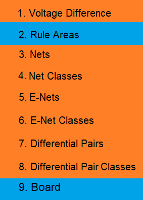
| Use hierarchy | The effective value for conductor clearance is set by checking
clearance rules in the following order. The first clearance value
that is found is used. Click the relevant row in the following
image for a description of where the value is set. Further information
regarding the clearance rules is provided in the Note
section below.
Note
|
|
| Use largest value |
The largest clearance value is used that is set in either the Design Rule sub-tab, Voltage Difference Clearance section in Constraint Browser, or in the Default design rule stack section in Rule Editor. In the following example, a clearance of 0.1 mm is set in the Default design rule stack, and a clearance formula of 0.00305 * Vdiff + 0.05000 is specified in the Clearance dialog.
Below approximately 16V, the clearance is defined by the Default design rule stack. Above this voltage, the clearance is defined by the formula as this produces the largest clearance values. |
Default attributes for signal
Sets default voltages for Nets that have no voltage defined in Constraint Browser.
When the voltage difference between conductors is calculated using the Creepage Check Results dialog, the Creepage results are affected by the voltage attributes below.
- If a Phase Group value is not set for both nets, or is different.
- For each net, the Low Voltage value of one net is compared with the High Voltage value of the other net.
- For each net, the High Voltage value of one net is compared with the Low Voltage value of the other net.
The largest difference is set as the Voltage
difference value in the Creepage
Check Results dialog.
- If the same Phase Group value is set for both nets.
- The Voltage, Low Voltage and High Voltage values are compared between each net. The largest difference is set as the Voltage difference value in the Creepage Check Results dialog.
- If Low Voltage or High Voltage values are not set, then the Voltage value is used instead. The Voltage, Low Voltage and High Voltage values are then compared between each net. The largest difference is set as the Voltage difference value in the Creepage Check Results dialog.
- If only Low Voltage or High Voltage values are set for a particular net, then these values are used for the missing Voltage, Low Voltage or High Voltage values. The Voltage, Low Voltage and High Voltage values are then compared between each net. The largest difference is set as the Voltage difference value in the Creepage Check Results dialog.
| Item | Description |
|---|---|
| Voltage [V] | The default voltage value of a signal. For a signal that is displayed in the Creepage Check Results dialog, this value is displayed, by default, if a voltage value is not specified for it. The above Note describes how this value is used in the Creepage Check Results dialog if a Voltage value is not defined in Constraint Browser. |
| Minimum voltage [V] | The most negative voltage a signal can carry. For a signal that is displayed in the Creepage Check Results dialog, this value is displayed, by default, if a minimum voltage value is not specified for it. The above Note describes how this value is used in the Creepage Check Results dialog if a Low Voltage value is not defined in Constraint Browser. |
| Maximum voltage [V] | The most positive voltage a signal can carry. For a signal that is displayed in the Creepage Check Results dialog, this value is displayed, by default, if a maximum voltage value is not specified for it. The above Note describes how this value is used in the Creepage Check Results dialog if a High Voltage value is not defined in Constraint Browser. |
| Phase group | Phase groups allow you to group elements, and can be used as
follows to change how the results are calculated. They are specified
in the Design
Rule tab in the Constraint
Browser: Signals section, Signals tab. When the voltage difference
between conductors is calculated, the Phase
group value is used as
follows.
See the above Note for further details on how the Phase group value is used in the Creepage Check Results dialog. |
Active clearance table stack for board
Allows you to assign the voltage difference clearance table stacks that you create in the Voltage difference clearance table stack section. If specified, then this clearance is referenced, by default, by the Creepage Check command. You can set default clearances for nets that have voltages defined or undefined.
| Item | Description |
|---|---|
| Between voltage defined net and undefined | Specify the voltage difference clearance table stacks that are referred to by the Creepage Check command for clearances between nets whose voltage is defined, and those whose voltage is undefined. These clearance table stacks are created in the Voltage difference clearance table stack section. |
| Between voltage defined nets | Specify the voltage difference clearance table stacks that are referred to by the Creepage Check command for clearances between nets whose voltage is defined. These clearance table stacks are created in the Voltage difference clearance table stack section. |
Voltage difference clearance table stack
Allows you to specify the clearance value that is applied to each conductor, for particular voltage ranges. Clearance values are set in the voltage difference clearance table that you select. These must be created previously in the Voltage difference clearance table section.
You can import a Voltage difference clearance table stack from the design rule library using the Import Design Rule Library (Partial) dialog.
| Item | Description | |
|---|---|---|
| Voltage difference clearance table stack box | Define the alphanumeric name of a voltage difference clearance table stack, and press Return or click Add. It is created, and added to the Voltage difference clearance table stack list. | |
| Add | Adds the voltage difference clearance table stack that you define to the Voltage difference clearance table stack list. Alternatively, press Return. | |
| Voltage difference clearance table stack list |
Displays the voltage difference clearance table stacks that you create using the Voltage difference clearance table stack box. Click an item to display it in the Conductor table. Note
Right-clicking an item allows you to delete or duplicate it. If you duplicate an item, specify its name in the displayed Duplicate dialog. |
|
| Conductor table | For the item that you click in the Voltage difference clearance table stack list, specify a voltage difference clearance table for each conductor layer by selecting it in the relevant drop down list. These must be created previously in the Voltage difference clearance table. | |
| Conductor layer | Displays the conductor layers for which voltage difference clearance tables can be selected. | |
| Clearance table | For each conductor layer, specify a voltage difference clearance table by selecting it in the associated drop down list. |
Voltage difference clearance table
Allows you to specify the clearance value that is applied when the voltage difference between conductors is within the appropriate range. If you specify values in this section, then a voltage difference above a defined threshold can be assigned a particular clearance value, and a voltage difference below the threshold can be assigned a different clearance value.
You can define clearances using either a clearance rule or formula. When clearance items are set, the Clearance/Voltage graph is populated. This shows the clearance values for each voltage difference range.
You can import a Voltage difference clearance table from the design rule library using the Import Design Rule Library (Partial) dialog.
| Item | Description | |
|---|---|---|
| Voltage difference clearance table name box | Define the alphanumeric name of a voltage difference clearance table, and press Return or click Add. It is created, and added to the Voltage difference clearance table name list. | |
| Add | Adds the voltage difference clearance table name that you define to the Voltage difference clearance table list. Alternatively, press Return. | |
| Voltage difference clearance table name list |
Displays the voltage difference clearance table names that
you create using the Voltage difference
clearance table name box. Click an item to display it in
the Voltage difference clearance table. Note
|
|
| New threshold box | Define a numeric boundary value for a voltage range. This determines
the point where the clearance value changes. Press Return
or click Add to add it to the Voltage difference clearance table.
For the first boundary value that you specify, two rows are created
in the Voltage difference clearance
table.
For each row, point the cursor in the Clearance column and click |
|
| Add button | The boundary value that you define is added to the Voltage difference clearance table. Alternatively, press Return. Values are listed in the table in order of voltage. | |
| Voltage difference clearance table |
The boundary values that you specify in the New
threshold box are listed in order of voltage. For each
row, point the cursor in the Clearance column and click Note
|
|
| Voltage difference [V] |
|
|
| Clearance | Allows you to specify a clearance value for each voltage range.
Either type in a value, or point the cursor in the Clearance column and click  to select a clearance
in the displayed Clearance dialog. These clearances are set in
the Design rule group section
of the Conductor
sub-tab, in the Conductor Clearance
tab of the Rule Editor dialog.
The contents of the row are immediately represented in the Clearance/Voltage graph. to select a clearance
in the displayed Clearance dialog. These clearances are set in
the Design rule group section
of the Conductor
sub-tab, in the Conductor Clearance
tab of the Rule Editor dialog.
The contents of the row are immediately represented in the Clearance/Voltage graph. Note If you specify a formula for the clearance using the Formula tab in the Clearance dialog, then this is displayed in the Clearance column, rather than a clearance value. |
|
| Clearance/Voltage graph | The clearance values for each voltage difference range in the
Voltage difference clearance table
are displayed graphically. These are displayed automatically when
you add values in this table. Specify a clearance value for each
row using the Clearance dialog. |
