
Automated Measurements
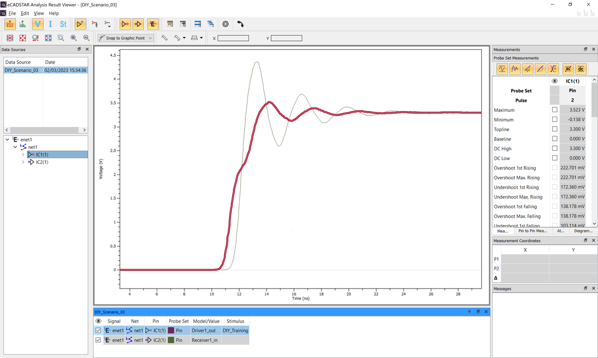
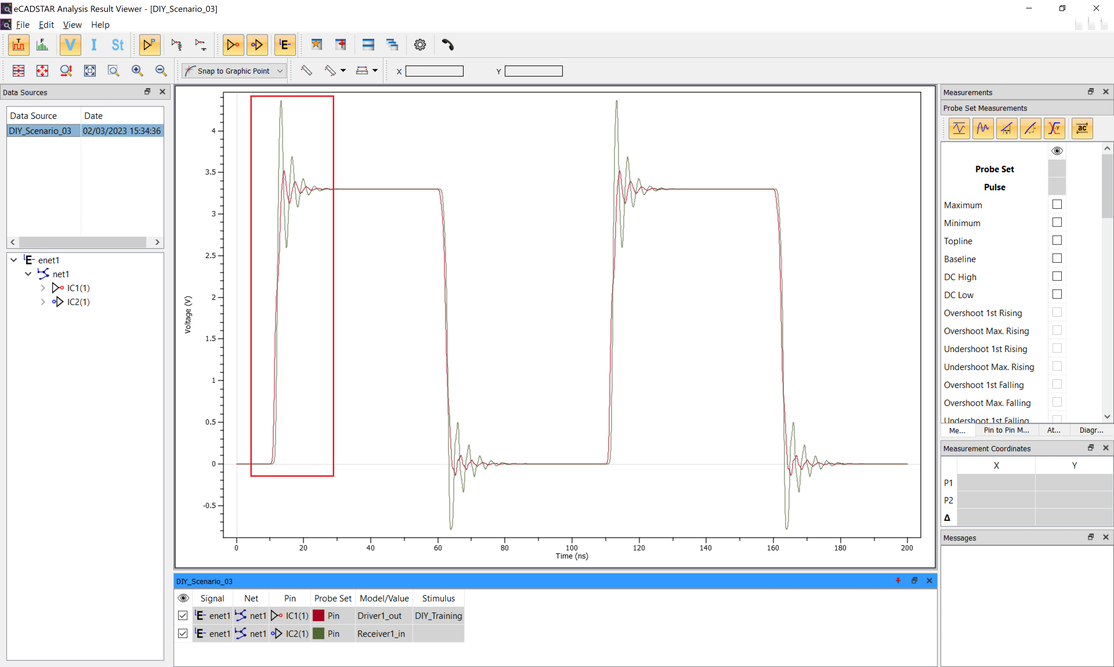
Analysis Result Viewer allows you to measure values and characteristics that are relevant to waveform verification. In this topic, you will learn how these values are calculated.
- In the work area set, ensure that the check box for IC2(1) is selected.
- Using the
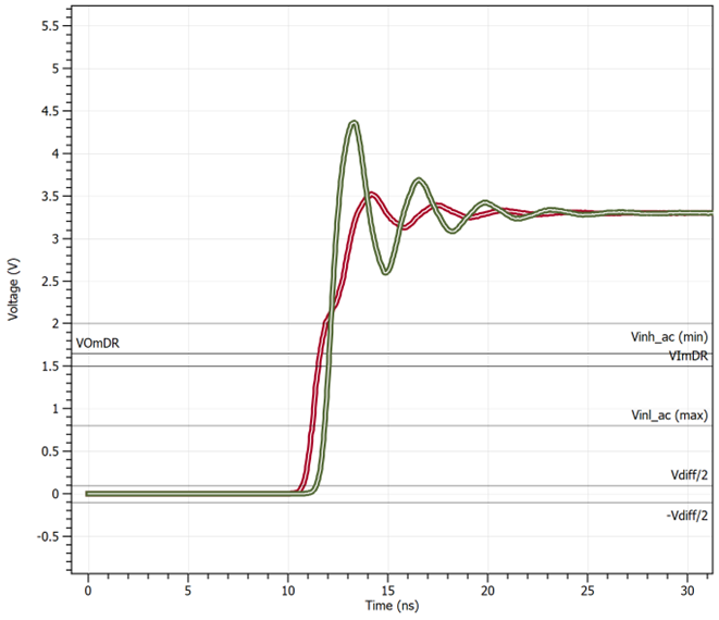
 Zoom
Area command, zoom in on the rising edge.
Zoom
Area command, zoom in on the rising edge.

- Use the Ctrl key
to select "IC1(1) and "IC2(1)".
- In the Attributes panel, click the Measurements tab.
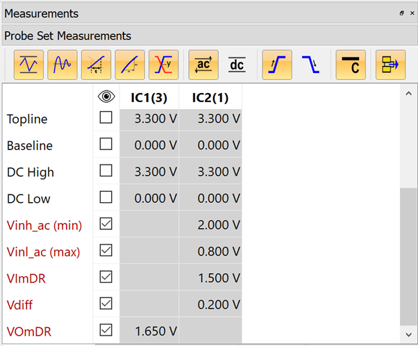
- In the Measurements tab, set the following display items.
This hides DC measurements, Falling Edge measurements and any unpopulated measurements. - In the Measurements tab, set the following items to be displayed.
| Item | Description |
|---|---|
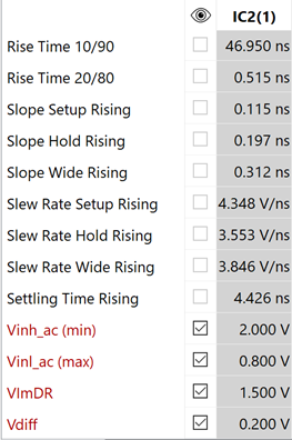
| Vinh_ac (min) | This is the voltage that a low-to-high going input waveform must reach in order to guarantee that the receiver will detect a high. In other words, reaching Vinh_ac is sufficient to guarantee a receiver state change. |
| Vinl_ac (max) | This is the voltage that a high-to-low going input waveform must reach in order to guarantee that the receiver will detect a low. In other words, reaching Vinl_ac is sufficient to guarantee a receiver state change. |
| VImDR | This is the input reference voltage for delay measurements. This is read from the IBIS Vth fields. If these values are not available, the IBIS Vinh and Vinl fields will be used. Both VImDR and VImDF will be set to (Vinh + Vinl) / 2. |
| VOmDR | This is the output reference voltage for delay measurements. This is read from the IBIS Vmeas fields. |
- In the Pin to Pin Measurements tab, set the Display to the following.
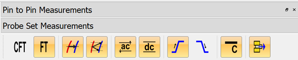
Hide Compensated Flight Time, Falling Edge measurements and any unpopulated measurements.
- For the flight times on the rising edge, note that the values are displayed.
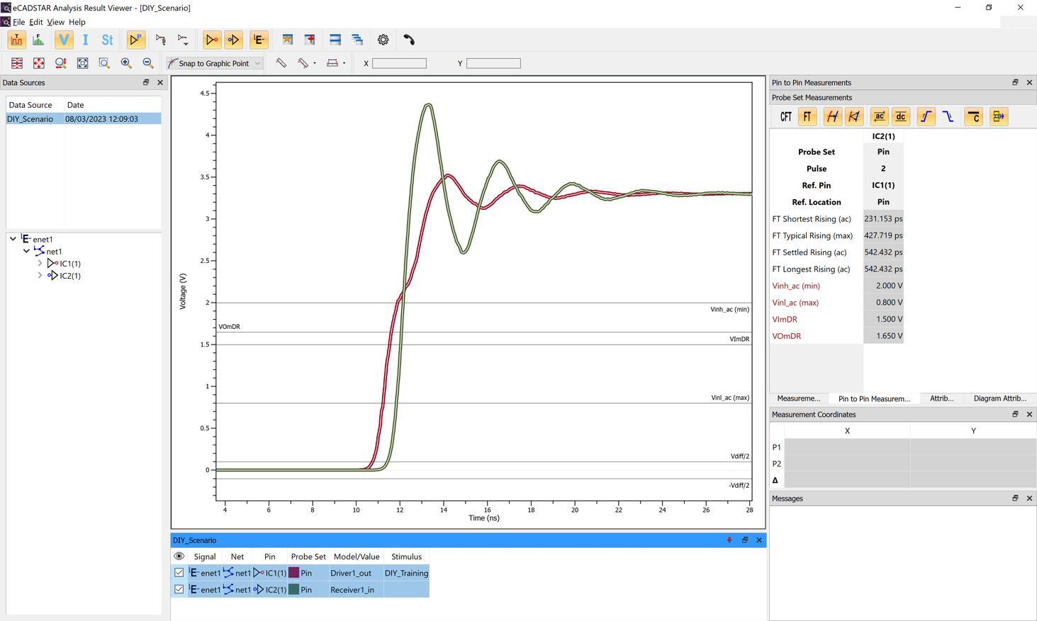
Flight Time is the interval between the driver pin reaching the driver threshold (VOmDR) and the receiver pin reaching the receiver threshold for the following items.
| Item | Description |
|---|---|
| Shortest | Indicates the time from when the driver pin crosses VOmDR to when the voltage at the receiver pin crosses the receiver's VInl_ac (max) or VInl_dc (max) threshold. It is the shortest time between the driver pin voltage crossing VOmDR and the receiver pin voltage being detected as a High. |
| Typical | Indicates the time from when the driver pin crosses VOmDR to when the voltage at the receiver pin crosses the receiver's VImDR threshold. |
| Longest | Indicates the time from when the driver pin crosses VOmDR to when the voltage at the receiver pin crosses the receiver's VInh_ac (min) or VIinh_dc (min) threshold. |
| Settled | Indicates the time from when the driver pin crosses VOmDR to when the voltage at the receiver pin finally crosses the receiver's VInh_ac (min) or VInh_dc (min) threshold. It includes the time taken for any ringing at the receiver pin to finally settle above the threshold. |
In this example, as the waveform crosses the threshold only once, the Settled time is the same as the Longest time.
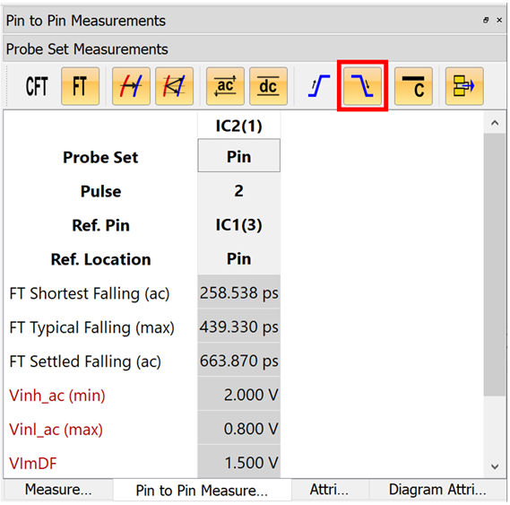
If required, Falling times can also be shown by selecting the Falling Edge icon.
-
Select the
 Display All button.
-
In the working set area, select “IC2(1)” and select the Measurements tab in the Attributes panel.
Measurements are automatically generated from the simulation waveforms as part of the simulation process.
-
Select the Display All button.
- Check the Maximum and Minimum measurements. The graph is updated.
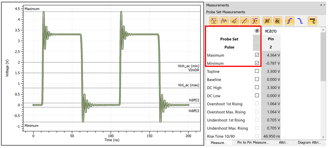
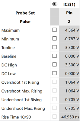
- Maximum is the highest voltage of the analyzed waveform.
- Minimum is the lowest voltage of the analyzed waveform.
-
Check the Topline and Baseline measurements. The graph is updated.
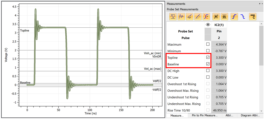
- Topline is the voltage that the signal settles to in a high state.
- Baseline is the voltage that the signal settles to in a low state.
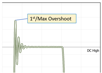
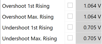
- Check the Overshoot 1st Rising and Overshoot Max. Rising measurements.
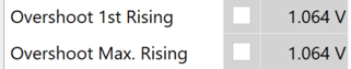
These report the differences between the maximum value that the rising edge of the receiver reaches and DC High.
-
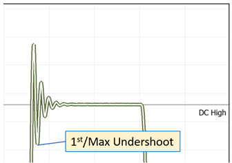
Check the Undershoot 1st Rising and Undershoot Max. Rising measurements.
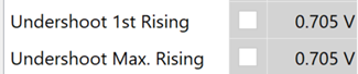
These report the differences between the undershoot voltage of the receiver and DC High for the rising edge.
Similar data is available for the Falling Edge of the waveform.
- Check the Rise Time 10/90 and Fall Time 10/90 measurements.
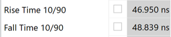
These are the times it takes for the voltage to transition between 10% and 90% of the voltage range from DC Low to DC High.
-
Check the Rise Time 20/80 and Fall Time 20/80 measurements.
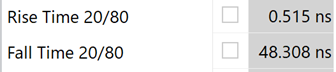
These are the times it takes for the voltage to transition between 20% and 80% of the voltage range from DC Low to DC High.
- Check the Slope Setup Rising and Slope Setup Falling measurements.
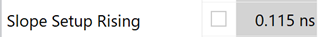

- Slope Setup Rising is the setup time measured from when the voltage crosses VImDR for the first time, until it crosses Vinh_ac (min) or Vinh_dc (min) for the last time.
- Slope Setup Falling is the setup time measured from when the voltage crosses VImDF for the first time, until it crosses Vinl_ac (max) or Vinl_dc (max) for the last time.
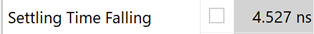
- Check the Settling Time Rising and Settling Time Falling measurements.
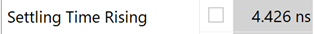
- Settling Time Rising is the time it takes for the ringing to settle within ±10% of the value of DC High.
- Settling Time Falling is the time it takes for the ringing to settle within ±10% of the value of DC Low.
In Eye pattern mode, various measurements are available that are not present in Time Domain mode, such as Opening Factor, Signal to Noise.
Manual measurements
- Select the Display All button.
- Use the Ctrl key to select “IC1(1)” and “IC2(1)”.
- Zoom into the area shown
- Then zoom further into the area shown.
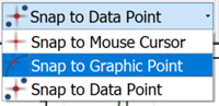
- Select
 Snap to Graphic Point.
 - Select
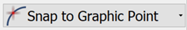
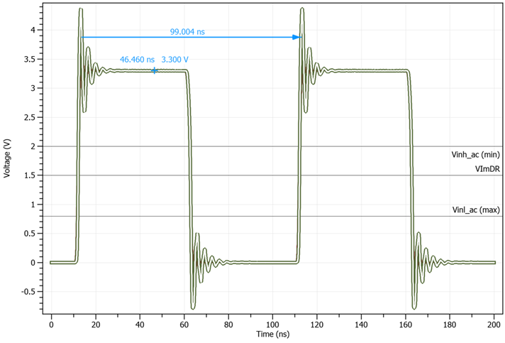
 Measure Point to Point. Note that the cursor will snap to the displayed waveforms.
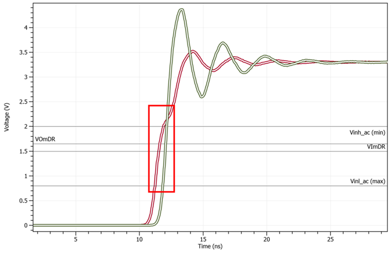
 - At the point where the output waveform (which is red in this case) crosses VOmDR, click and hold to start the measurement.
- At the point where the input waveform (which is green) crosses Vinl_ac (max), release the mouse button.
The measurement is added to the display showing time and voltage change.
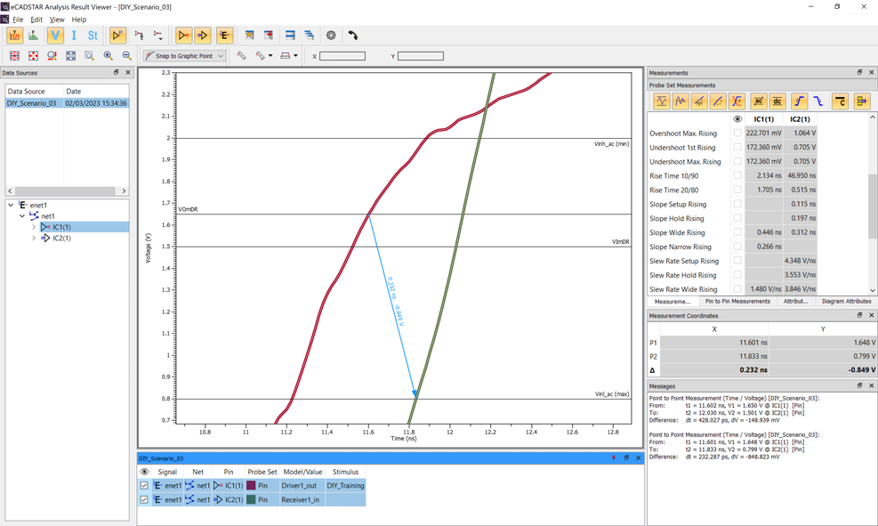
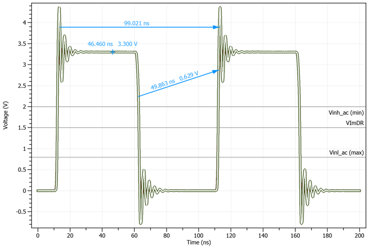
- Select Measure Point to Point. Note that the cursor will snap to the displayed waveforms.
- Measure from VOmDR to Vinh_ac (max).
- Measure from VOmDR to VimDR.
Measurements are displayed on the canvas and are also shown in the Messages panel.
These measurements can be verified against the automated measurements made in the Pin to Pin Measurements panel.
- Select the Display All button.
-
In the Messages panel, use the Assist Menu (RMB) and select Clear. All measurements will be removed from the canvas.
-
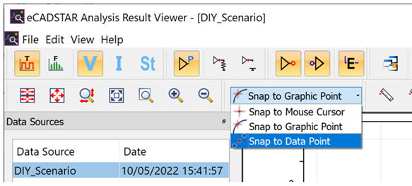
On the toolbar, change the snap mode to Snap to Data Point.
-
Select "IC2(1)" and click
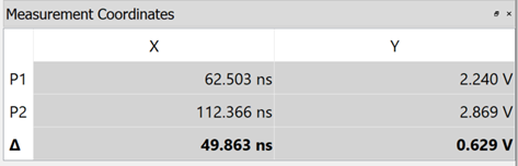
 Measure Point on the toolbar. When moving the cursor over the waveform, you can see that it moves based on the data plotted on the waveform.
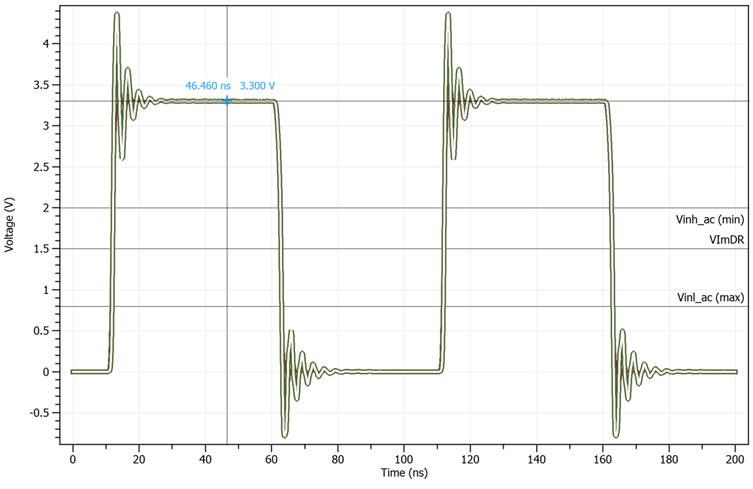
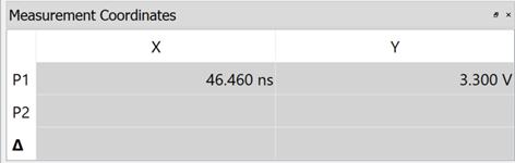
You can view the exact values in the Measurement Coordinates panel.
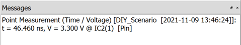
Clicking the waveform allows you to view the results of interactive measurements in the Messages window.
-
On the toolbar, change the snap mode from Snap to Data Point to Snap to Graphic Point.
- On the toolbar, click
 Measure Nearest Points (Horizontal) to activate it.
 - Move the cursor over the waveforms to see the difference between snap modes. The cursor follows a graphical view of the waveform, and measures between horizontal locations on it.
- Click to place take a measurement.
-
On the toolbar, click
Measure Point to Point. Within the chart area, click and drag from one point on the waveform to a second point on the waveform. Then release the mouse button.
The time difference [dt] and voltage difference [dv] between the two specified points can be confirmed.
-
On the menu bar, click File > Exit to close eCADSTAR Analysis Result Viewer.
You have now completed the SI Analysis DIY Training, and can close all eCADSTAR applications.
This task is demonstrated in the following video.
