
Introduction to Analog Simulation
The Analog Simulation DIY training guide describes how to operate eCADSTAR’s SPICE Controller interface with LTspice. This allows you to perform and analyze analog simulations.
What is SPICE?
The most practical method for checking the operation of an electronic circuit is to physically create the circuit as hardware. As an example, if there are problems caused by the physical nature of microcircuits in integrated circuit design, then it may be difficult to deduce the cause by performing verification using normal discrete components. Whereas creating the IC and testing it may yield good results, this would be costly and time consuming.
In 1973, a solution to overcome this problem was published in the following dissertation paper by L. W. Nagel and D. O. Pederson of the University of California of Berkeley (UCB).
Simulation Program with Integrated Circuit Emphasis (SPICE).
Although SPICE was developed to analyze integrated circuits, it could perform analysis irrespective of circuit size, voltages or electrical currents. It was therefore widely used. In 1975, SPICE became SPICE2 after many improvements. In 1981, SPICE2G6 was released. This was a reliable product, with high precision. SPICE was "public domain” software. This means it was freely available to use. However, there was no support for business users of SPICE at that time.
At the start of the 1980s, a version of SPICE for business users became available. This provided an appropriate level of service and support. After this, SPICE3, which was rewritten from the Fortran language to C, was released. SPICE3F4 was released in 2003. For this reason, many electronics corporations obtained source code from the Berkeley SPICE and improved it by incorporating their own knowledge into the system.
Advantages of using a SPICE Simulator
- The verification process is performed on a computer. This eliminates the time and expense of physically creating the circuit.
- You can construct the circuit and make changes to constants with a netlist. This makes it simple to study the design.
- Setting input conditions as close to reality as possible will produce more precise verification results. For example, if you use a device model that considers capacitance parameters, and model the board pattern as transmission lines, you can get measurements which are almost identical to actual results. This includes the operations of high frequency circuits.
- You can perform verification in accordance with real manufacturing technology. For example, if you consider the variations of circuit constants and changes in power during the analysis, then you can predict the yield of the product. This allows you to study the trade-off with the cost of components.
- You can create an ideal schematic design, using your chosen device model. This could then be analyzed without being constrained by restrictions in manufacturing technology. This allows you to verify the basic structure of the circuit. You could then design it, assuming that restrictions are removed as improvements are made in manufacturing technology.
A SPICE simulator is a simple arithmetic batch program for dealing with input information. Appropriate and accurate input information is required to ensure relevant results are obtained from the tool
- If the circuit or analysis conditions are incorrect, then they incorrectly processed and the wrong results are obtained by the analysis.
- The simulator must be given an input that is appropriate for the degree of precision required from the analysis output. Always using an ideal model will not deliver accurate results. Analyzing high frequencies without considering circuit transmission line characteristics will not deliver results that match the measurements from the physical circuit.
The simulator will not necessarily produce the same measurements as in practice, in all cases. Actual measurements are subject to limitations due to measurement technology. Also, all factors present in SPICE are included as input conditions, which sometimes requires a large amount of effort. The accuracy of SPICE depends on the quality of the information that is input. In practice, you should consider the appropriate trade-off with the effort required to prepare all the information.
What is the SPICE Controller?
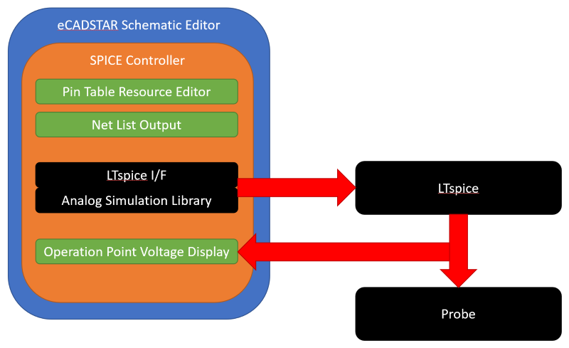
Using eCADSTAR SPICE Controller, you can create a SPICE format net list from the relevant schematic design, and perform simulation using the LTspice simulator. The simulation process is described below.
- Schematic data is created in eCADSTAR Schematic Editor. This also involves setting some properties for the SPICE Controller.
- Create a net list for SPICE Controller using the Netlist Out command.
- Use the SPICE Controller Manager to set the power, input signal and analysis conditions. Create a SPICE netlist for the LTspice simulator.
- Perform analysis using the LTspice Simulator.
- Confirm the analysis results of the LTspice simulator with the waveform display tool. This file provides the input data for the LTspice simulator. It consists mainly of element statements that represent the circuit being analyzed, and analysis statements that define analysis conditions.
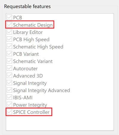
A license for eCADSTAR Schematic Editor and SPICE Controller features is required for this training. Check this as follows.
- On the eCADSTAR Schematic Editor ribbon, click File > Configuration > Product Settings. The Product Settings dialog is displayed.
- In the Product Settings dialog, select License Settings. The licensed features for the eCADSTAR items are displayed in the Requestable features box, shown below.
Training Files
The following schematic designs are provided for this DIY training on SPICE Controller.
- ASim1.sdes
- ASim2.sdes
Prerequisites
- Ensure that the Analysis Module Library is referenced before starting the training.
- Ensure that the LTspice application is installed and configured for operation in eCADSTAR.
- Familiarity with eCADSTAR Schematic Editor is required.
Referencing the Analysis Module Library
- On the Start menu, click eCADSTAR [Version] > Schematic Editor [Version]. eCADSTAR Schematic Editor is launched.
- In the File tab, click Configuration > Product Settings. The Product Settings dialog is displayed.
- Select Library
in the list. Click
 for the Library
directory. The Open Library dialog is displayed.
for the Library
directory. The Open Library dialog is displayed. - Browse to the following location and click Select Folder: C:\Users\Public\eCADSTAR\eCADSTAR [Version]\Analysis\Library.
You may need to restart all eCADSTAR schematic and PCB applications for this change to take effect.
