
Task 6: Placing the Design
In this task you will place components on the board that you have already created. During the task, you’ll place the components both individually and within a group, along with placing by coordinates and aligning the parts. To manually place individual components:
- Continue to use your design from the previous task.
- Ensure that layer Conductor–1 is selected. Select component CN3 by pointing the cursor at it, pressing the Shift key, and dragging it into position on the board. Use the placement diagram below to estimate the placement location, release the mouse button when ready to place the component.
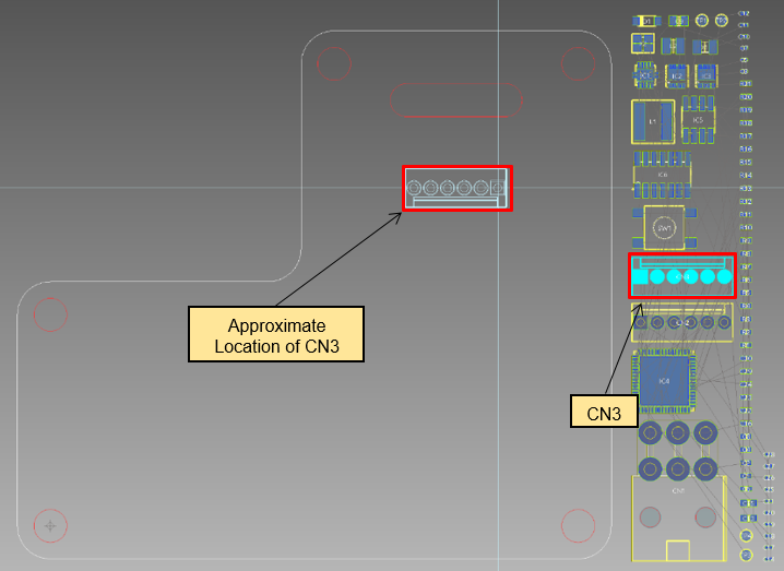
Figure 1: Manually Placing Components
- With the component placed, right-click and select Rotate about reference point on the assist menu to rotate it 90 degrees.
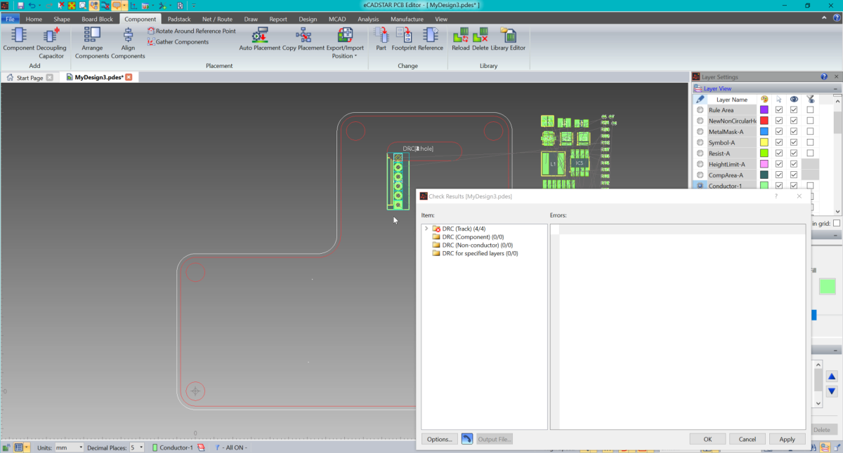
If Post Check is enabled, then the Check Results dialog is displayed if the component fouls the slot. Click OK to close the dialog.
- Rotate the component another 90 degrees.
- Right-click and select Placement Side A on the assist menu to place the component on the other side of the board. Next, reposition the component.
The next task covers the placing of components by coordinates.
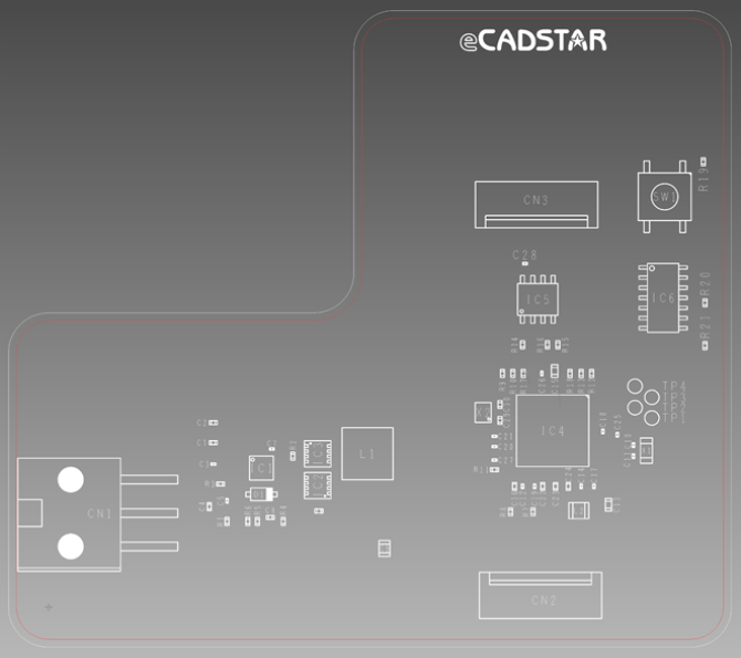
Figure 2: Completed Component Placement Diagram
| Reference | X coordinate | Y coordinate | Placement Side | Rotation |
| C20 | 55.5 | 20.2 | A | 0 |
| C21 | 55.5 | 21.5 | A | 0 |
| C22 | 61.5 | 15.2 | A | 90 |
| C23 | 63.1 | 15.2 | A | 90 |
| C24 | 64.7 | 15.2 | A | 90 |
| C25 | 70.8 | 21.7 | A | 270 |
| C26 | 61.4 | 29.4 | A | 270 |
| C27 | 55.5 | 18.5 | A | 0 |
| C28 | 59.3 | 43.2 | A | 0 |
| C29 | 56.2 | 23.5 | A | 90 |
| C30 | 56.2 | 25.5 | A | 270 |
| C1 | 20.5 | 20.7 | A | 0 |
| C2 | 20.5 | 23.2 | A | 0 |
| C3 | 20.5 | 18 | A | 0 |
| C4 | 20 | 12.65 | A | 90 |
| C5 | 22.2 | 13.4 | A | 90 |
| C6 | 33.65 | 12.1 | A | 180 |
| C7 | 27.8 | 19.9 | A | 0 |
| C8 | 27.6 | 11.3 | A | 0 |
| C9 | 41.8 | 7.4 | A | 90 |
| D1 | 26.5 | 14.2 | A | 180 |
| SW1 | 76.7 | 51.6 | A | 90 |
| L1 | 39.7 | 19.3 | A | 0 |
| L2 | 66 | 12.15 | A | 180 |
| IC1 | 26.5 | 17.5 | A | 270 |
| IC2 | 33.5 | 15.3 | A | 90 |
| IC3 | 33.5 | 19.3 | A | 270 |
| IC4 | 62.735 | 22.2 | A | 180 |
| IC5 | 60.9 | 38.7 | A | 0 |
| IC6 | 76.5 | 38.9 | A | 270 |
| R10 | 57.8 | 29.4 | A | 270 |
| R11 | 55.5 | 17.3 | A | 0 |
| R12 | 67.6 | 29.4 | A | 270 |
| R13 | 66.3 | 29.4 | A | 270 |
| R14 | 59 | 33 | A | 90 |
| R15 | 63.4 | 33 | A | 90 |
| R16 | 62.1 | 33 | A | 90 |
| R17 | 59.1 | 29.4 | A | 270 |
| R18 | 64.9 | 29.4 | A | 90 |
| R19 | 81.5 | 56 | A | 270 |
| TP1 | 75.1 | 23.8 | A | 0 |
| TP2 | 73 | 25.1 | A | 0 |
| TP3 | 75.1 | 26.4 | A | 0 |
| TP4 | 73 | 27.8 | A | 0 |
| R20 | 81.7 | 38.275 | A | 90 |
| R21 | 81.7 | 32.9 | A | 90 |
| R1 | 22.2 | 10.8 | A | 90 |
| R2 | 30.4 | 19 | A | 270 |
| R3 | 21.4 | 15.5 | A | 180 |
| R4 | 29.2 | 10.8 | A | 270 |
| R5 | 26 | 10.8 | A | 270 |
| R6 | 24.8 | 10.8 | A | 270 |
| R7 | 60.3 | 12 | A | 90 |
| R8 | 57.5 | 12 | A | 90 |
| R9 | 56.5 | 29.4 | A | 270 |
| CN1 | 10.05 | 16.05 | A | 270 |
| CN2 | 54.88 | 1.5 | A | 0 |
| CN3 | 67.1 | 50.6 | A | 180 |
| X1 | 74.425 | 19.7 | A | 90 |
| X2 | 54.1 | 24.5 | A | 90 |
| C10 | 72.8 | 20.4 | A | 270 |
| C11 | 72.8 | 19 | A | 90 |
| C12 | 59 | 15.2 | A | 270 |
| C13 | 69.7 | 12.9 | A | 270 |
| C14 | 66.3 | 15.2 | A | 90 |
| C15 | 63 | 29.7 | A | 270 |
| C16 | 58 | 15.2 | A | 90 |
| C17 | 67.9 | 15.2 | A | 90 |
| C18 | 69 | 22.1 | A | 270 |
| C19 | 60.5 | 15.2 | A | 90 |
Table 1: Component Placement Details
This task is demonstrated in the following video.
Related Topics
Arrange Components
Placement Tools
DRC for Component Placement
