
Task 7: Placing Components by Coordinates
In this task, you will place a component using coordinates.
- Continue to use your design from the previous task.
- Open the Component Selector panel
 .
. - Select the Move on Selection check box.
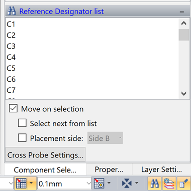
Figure 1
- Click the Cross Probe settings button.
- Set Cross Probe to Select only, and click OK.
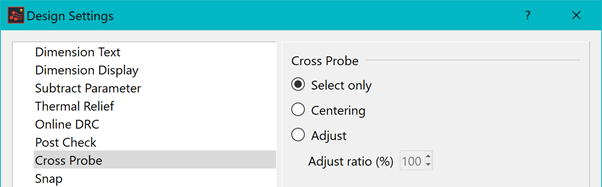
Figure 2
- Scroll down the list of components and click IC4, as shown below. IC4 is now highlighted to be on the cursor.
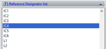
Figure 3: Reference Designator List Showing IC4
- Right-click, and select Input Coordinate.
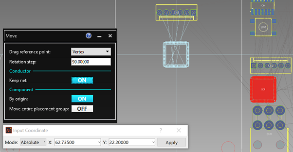
Figure 4: Placing a Component by Coordinates
- Set the rotation by right-clicking and selecting Rotate 180.
- Set the coordinates as follows: X = 62.735, Y = 22.2.
- Click Apply. IC4 is now placed at the location specified.
Figure 5: The Placed Component
-
Place IC1, IC2 and IC3 using the same technique. The coordinates are as follows:
- IC1 X = 26.50000 Y = 17.5000 Rotation 270
- IC2 X = 33.50000 Y = 15.3000 Rotation 90
- IC3 X = 33.50000 Y = 19.3000 Rotation 270
- On the eCADSTAR PCB Editor ribbon, select Component > Add > Component. The Add Component dialog is displayed.
- In the Add Component dialog, select By footprint.
- You will now place fiducials from the Library using this dialog.
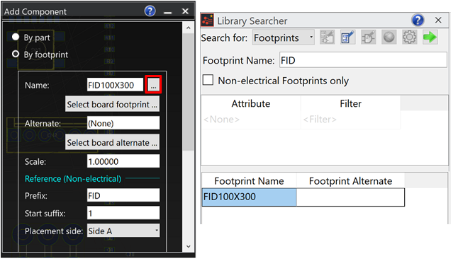
Figure 6: The Placed Fiducial
- The Footprint name is "FID100X300". Select this by clicking "…", and changing the search to Footprints in the Library Searcher. Enter the start of the footprint name as "FID".
- Pass this to the Add component
dialog by clicking the
 button,
or by double-clicking the component name in the Library Searcher.
button,
or by double-clicking the component name in the Library Searcher. - In the Add Component dialog, section Reference (Non-electrical), set Prefix to "FID" and Start suffix to "1". Set Placement side to "Side A".
- The coordinates for placement are as follows:
- FID1 X = 6.90000 Y = 0.0000 Rotation 0
- FID2 X = 74.00000 Y = 0.0000 Rotation 0
- FID3 X = 74.00000 Y = 70.0000 Rotation 0
As an alternative method of placement, select the Snap button as shown below.
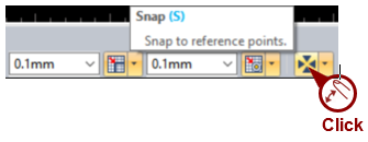
Figure 7: The Snap Function
The Snap function allows a component to be snapped to another object or specific location.
If the Snap function is enabled, then the Component Grid for placement is ignored.
You have now placed components by coordinates. This is demonstrated in the following video.
Now that you have covered the various ways to place parts, you will align them in the next task.
Related Topics
Arrange Components
Placement Tools
DRC for Component Placement
