
Task 8: Aligning Components by Location
In this task, you will select a group of components and place them on the board at a specific location.
- Continue to use your design from the previous task.
- Open the Component Selector panel
 .
. - Select capacitors C14, C17, C22, C23 and C24 from the Component Selector panel. You can select multiple components using the Ctrl key.
- Drag the components to the right of the PCB, and click Rotate 90 on the assist menu. The capacitors are rotated by 90 degrees. Place them further to the right of the arranged components.
- Re-arrange the components so that they are ordered from left to right as follows: C22, C23, C24, C14, C17.
- Close the Move command.
- Frame select the capacitors using the mouse.
- On the Component tab, click Align Components and set all parameters as shown below.
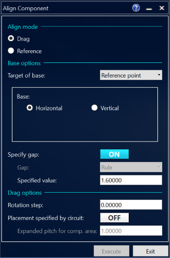
Figure 1: The Align Components Dialog
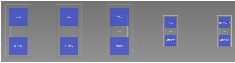
Figure 2: Aligned Components
-
Place the arranged components below IC4, as shown below. Add C16, C12 and C19 to the left.
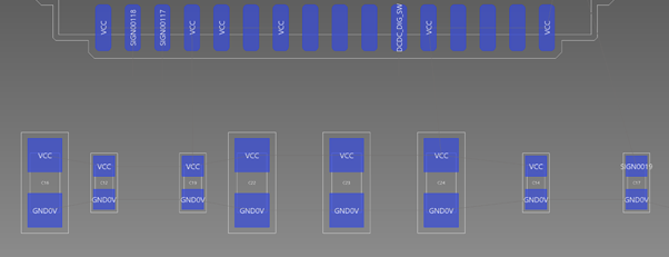
Figure 3: Placed Components
-
Place the remainder of the components on the board in accordance with the placement diagram displayed in Task 6.
This task is demonstrated in the following video.
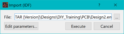
- Alternatively, you can import the placement of the design using the Import (IDF) command.
- Click Import > IDF on the Design tab.
- Click the
 button.
 - Select DIY.emn and click Open.
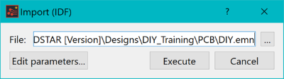
- Click Execute.
- In the displayed dialog, click Yes.

Components have now been placed within the design.
You will now move on to DRC for component placement.
