
The eCADSTAR PCB Editor Interface
In this topic you will look at the eCADSTAR PCB Editor interface. The following window is displayed when a PCB design is opened. The functions shown in each box are explained below:
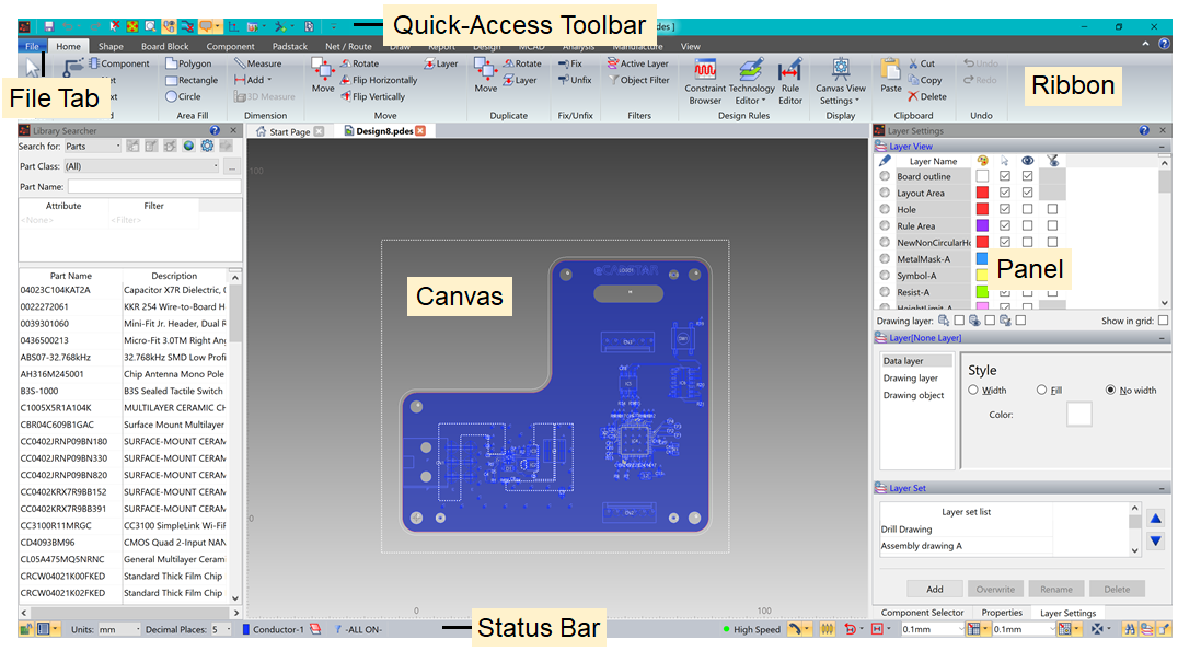
Figure 1: Exploring the eCADSTAR PCB Editor Interface
Each area shown in the above image is described in more detail below.
Features of the eCADSTAR PCB Editor interface
- Ribbon: contains the various categories from which options are selected. It is a layered element consisting of tabs, groups and controls.
- Canvas: displays the relevant PCB design.
- File Tab: allows you to execute operations on files, and provides general functions for application setting. These include the opening and closing of files, and saving and printing data.
- Quick Access Toolbar (QAT): allows you to select frequently-used commands. This toolbar can be customized to display the commands that you find most useful.
- Panels: the Layer Settings, Component Selector and Properties dialogs are provided as panels. You can drag and dock these panels, as required.
- Status Bar: contains the Message Log, Units, Active layer, Object filters and Cross Probe functions. DRC control, grids, snap and panel controls are also available. These allow you to quickly make changes to frequently-changed options.
3D View
On the View tab, click 3D View. The view mode will change, and a 3D compass will appear in the lower-right corner of the window. In this mode, strokes will still work, as well as the default keyboard pan X/Y and zoom functions. Clicking 3D View again will set the view back to 2D mode.
- To change the 3D view point use the 3D compass, shown in the bottom-right side of the screen.
- Dragging a handle changes the view point in the direction of the handle.
- Dragging a section other than the handles rotates the 3D compass in any direction.
As well as using the 3D compass, you can also select from seven preset views. You can use the Rotate operation, located in the 3D group, and then click directly in the window to change the view.
Application Settings
The Application Settings dialog is displayed by selecting File > Configuration > Application Settings on the eCADSTAR PCB Editor ribbon. This dialog contains numerous menus that allow you to define parameters. These include the following:
- Display settings
- Error Mark
- Canvas Information
- Save
- Interaction
- Area Fill Settings
- Technology
- Input Photo Data
- Hole Drawing
- Check Results
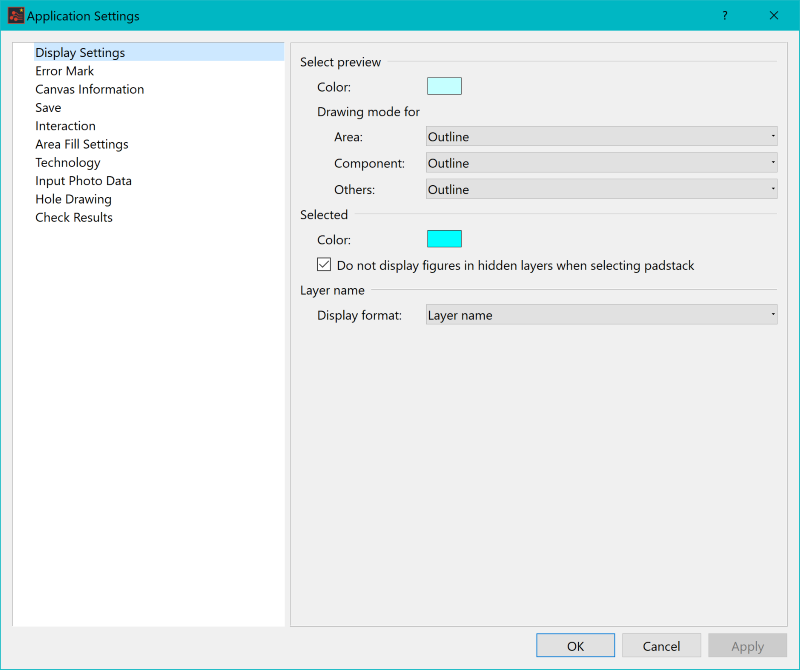
Figure 2: The Applications Settings Menu
Tooltips
Tooltips provide extra information when you hover over items. There are two different types of tooltips in the eCADSTAR applications:
- Quick Tooltips on the ribbon, providing the name of the item and a brief description of what the button does or launches.
- Help Tooltips in dialogs, providing an extract from the Help relating to the item, field or button, as a brief description of what the item, field or button does (where available).
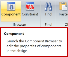
Figure 3: Quick tooltips on the ribbon
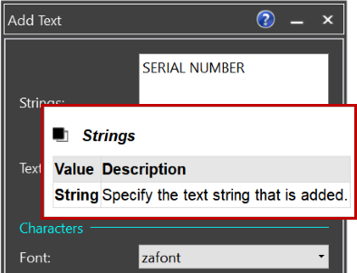
Figure 4: Help tooltips for items, fields or buttons.
Help
Manuals for how to operate eCADSTAR
and its functions are not provided as printed media; they are only available as Online Help.
The Online Help can be accessed at any time by clicking on the Help icon displayed ( ![]() or
or  ) in the top right corner of the Application, Command dialog or Dialog. Alternatively, it can be accessed by pressing the F1 key or from the File tab,
select Help.
) in the top right corner of the Application, Command dialog or Dialog. Alternatively, it can be accessed by pressing the F1 key or from the File tab,
select Help.
On startup, the Help page displayed will be relevant to the current application / command / dialog.
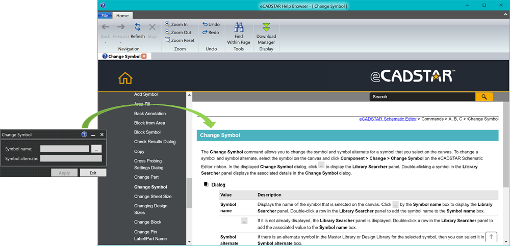
Figure 5:
Applications and Command dialogs include a Help ![]() symbol that, if clicked, takes you to the relevant
part of the Online Help
symbol that, if clicked, takes you to the relevant
part of the Online Help
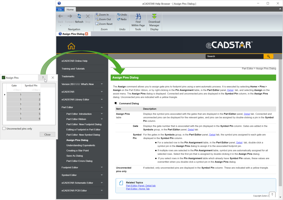
Figure 6:
Dialogs include a Help symbol that, if clicked, takes you to the relevant
part of the Online Help
Assist Menu
The Assist Menu provides a shortcut to commands relating directly to the area/object selected. Open the Assist menu for an object or area within the workspace by clicking the right mouse button either in a specific area or on a specific object.
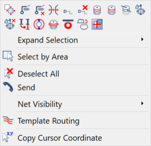
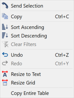
Figure 7: Examples of Assist Menus
Selection with the Cursor
Selection with the cursor works slightly differently depending on the eCADSTAR application. As a general rule:
- Select a single object by left clicking once on the object
- Select multiple objects by holding down the CTRL key while left clicking on the multiple objects
- Select all objects within a frame drawn by holding down the left mouse button and dragging across the objects required
- Select the whole component by holding down the SHIFT key while left clicking anywhere on the component.
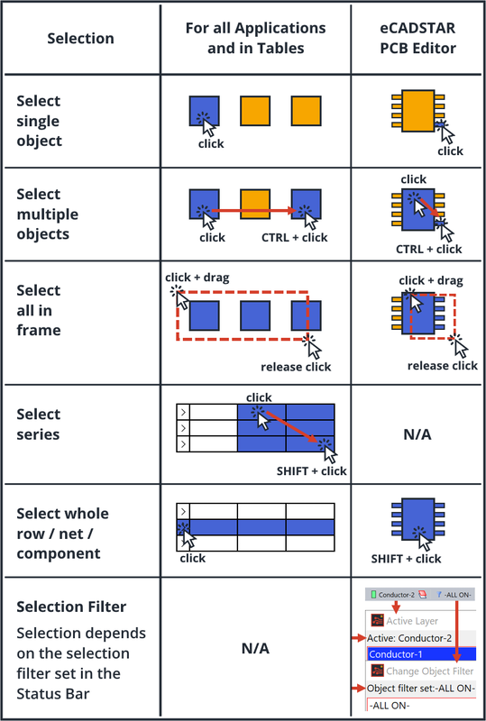
Figure 8: Selection with the Cursor
Stroke Commands
Stroke commands allow you manipulate the view of the canvas without moving the cursor away from the canvas. Alternatively, the Zoom buttons on the ribbon can be used.
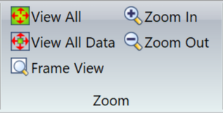
Figure 9: Zoom buttons on the View Ribbon
To enter a stroke command, hold down the right mouse button and drag the cursor in the direction / pattern required, as per the diagram below.
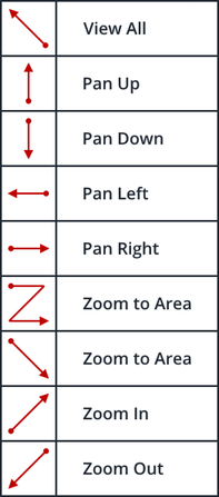
Figure 10: Stroke Commands
Adjust Pan Step and Zoom Ratio in: File > Configuration > Product Settings: Canvas Operation.
Shortcut keys
Shortcut keys allow you activate commands quickly without moving the cursor away from the canvas
Alternatively, the buttons on the ribbon or the Assist Menu can be used.
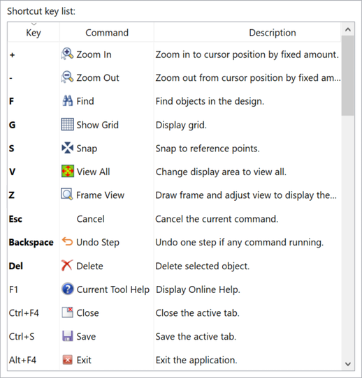
Figure 11: Stroke Commands
Shortcut keys can be fully customized and shared:
- Add shortcut keys for other commands
- Edit key for commands
- Delete shortcut keys not required
- Save and load the shortcut key list.
Access the shortcut keys list in: File > Configuration > Shortcut Key Settings
Training Files
The training library that is required in this course is automatically installed onto your machine when you use the installer.
You now understand the basic operation of eCADSTAR PCB Editor. You will create your own design in the next section.
Close any designs that are open in the eCADSTAR PCB Editor.
