
Task 3: Generating a Rectangular Pad
Pads are typically used in the creation of padstacks, including padstacks that are used in testpoints and Fiducials. Pads are also used for thermal relief, resist and metal mask (solder paste) openings and vias.
Generating a Rectangular Pad
In this task, you will create the pads that will be used to build up your own library parts, including a Small Outline Integrated Circuit (SOIC), and a through-hole connector.
- On the eCADSTAR Library Editor ribbon, click Home > Editors > Pad. The Pad Editor dialog is displayed.
- In the Pad Editor dialog, Pad Shape box, select Rectangle.
- In the Pad Editor dialog, click Add Pad. "NewPad-1" is created.
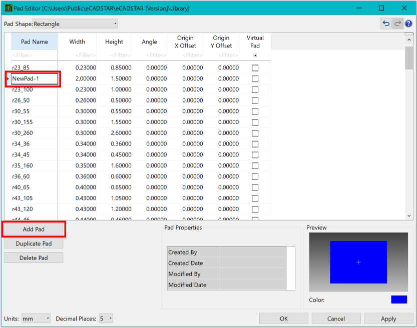
Figure 1: Adding a Pad
- In the Pad Name column, change the name of the pad to "DIY-r207_66".
- In the Width column, change the width of the pad to "2.07000".
- In the Height column, change the height of the pad to "0.66000".
- In the Angle, Origin X Offset and Origin Y Offset columns, leave the values at "0.000". Leave Virtual Pad unselected.
Note
Virtual pads are used within starpoint components to allow multiple nets to be connected at a single point.
Virtual pads are used within starpoint components to allow multiple nets to be connected at a single point.
- In the Pad Editor dialog, click Apply. The Pad Editor dialog remains open.
- When the Warning dialog is displayed, click Yes.
- Repeat the above task to also create a 2.27mm x 0.86mm pad named "DIY-r227_86". Both newly-created pads are shown below.
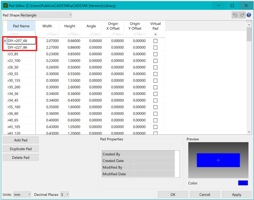
Figure 2: Created Pads
- Close the Pad Editor by clicking OK.
This task is demonstrated in the following video.
