
Setting Up Components
Detecting Types of Components
To perform SI analysis, component types (ICs, resistors, and so on) and values must be correctly detected. Component types comprise the following.
| Component type | Icon |
|---|---|
| Resistor |

|
| Inductor |

|
| Capacitor |

|
| Diode |

|
| IC |

|
| Connector |

|
| Others |

|
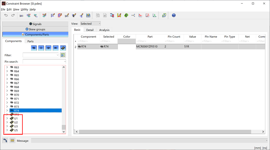
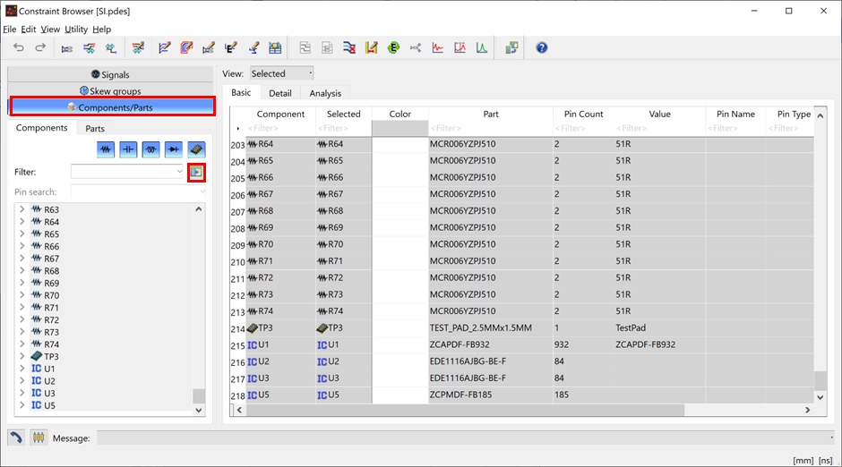
- On the ribbon, click Home > Design Rules > Constraint Browser. Constraint Browser starts.
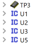
- Click the Components/Parts button to check the contents of the tree in the Components tab.
- In the design data, U is used as the IC reference header. Note that the header U is not identified as the component reference designator for ICs.
- Components with header U
are represented by the
 icon for other components.
Changing the Component Type
- On the Start menu in Windows, click eCADSTAR [Version] > Library Editor [Version]. eCADSTAR Library Editor starts.
- In the File tab, click Open Library. Alternatively, click Open on the Home tab. The Select Folder dialog is displayed.
- Browse to the following Library location, and click Select Folder: C:\Users\Public\eCADSTAR\eCADSTAR [Version]\Analysis\Library.
- On the ribbon, click Home > Editors > E-Net Definition. The E-Net Prefix Definition dialog is displayed.
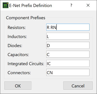
- Add U to the text in the Integrated Circuits box in the Component Prefixes section. To define a combination of multiple component headers as shown in the image, specify multiple character strings by delimiting them using spaces.
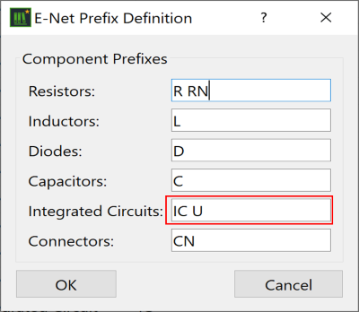
- Click OK and exit eCADSTAR Library Editor.
- On the ribbon in eCADSTAR PCB Editor, click Home > Design Rules > Constraint Browser. The Constraint Browser is displayed.
- On the Constraint Browser menu bar, click Utility > E-Net Prefix Definition. The E-Net Prefix Definition dialog is displayed.
- Click Update.
- Close the displayed message by clicking Yes. Note that U is appended to IC in the Integrated Circuits box.
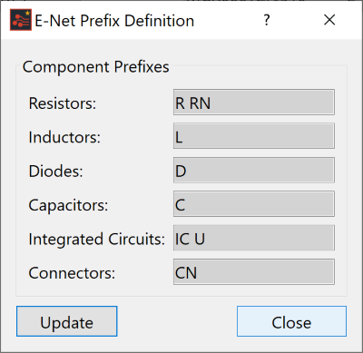
- Close the dialog.
- In Constraint Browser,
select Utility > Reconstruct E-Net
 on the main menu.
This updates the component categorization in the Constraint
Browser tree.
on the main menu.
This updates the component categorization in the Constraint
Browser tree. - Select Yes in the displayed message box to proceed.
- Check the contents of the tree in the Components
tab in Constraint Browser. The
icon for each component with a reference designator starting with
U is changed to the
 integrated circuit icon.
Setting Component Values
The values of passive components, such as series termination resistors, affect the results of SI analyses. Values of passive components are already registered in the eCADSTAR library, and are ready only when the items are used in a design.
Assigning Device Models
To perform SI analysis, assign analysis device models that are registered within the design’s simulation library to components in the design. The following methods can be used to assign analysis device models.
- In the Select Device dialog, separately specify a device model to manually assign it to components.
- Alternatively, use the Reload Simulation Library button to automatically assign analysis device models based on the model IDs or names in the design’s simulation library.
- In Constraint
Browser, Open the Components tab,
and click
 Select all items. Component information is
displayed in the table on the right.
Select all items. Component information is
displayed in the table on the right.
- In the table on the right, switch to the Analysis tab and check the contents under Device Name. Note that there are no simulation devices assigned.
- On the Constraint Browser menu, select Utility > Reload Simulation Library.
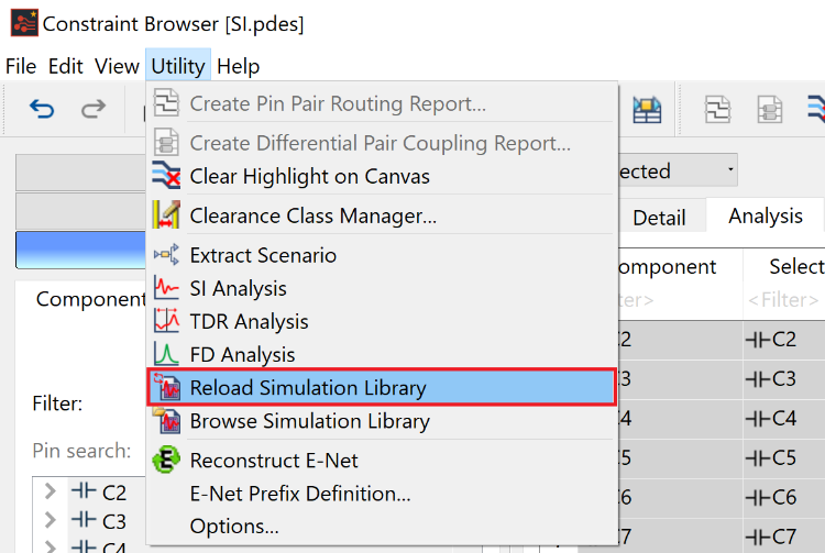
This starts the process to load and automatically assign simulation devices against components within the design. The assignment will attempt to match the component Part Name to the ID that you specify in the Simulation Library Browser.
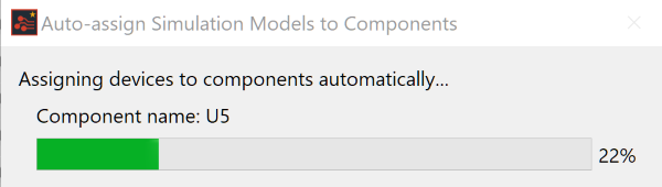
When completed, the Auto-Assign
Simulation Models to Components report is displayed. This shows
details of the failed and successful Simulation Device assignments.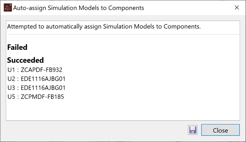
- Click Close in the report dialog. When devices are assigned to components, a report dialog is displayed which shows the component pins that are not assigned to a pin model. This occurs when the pin on the component is not connected to a net.
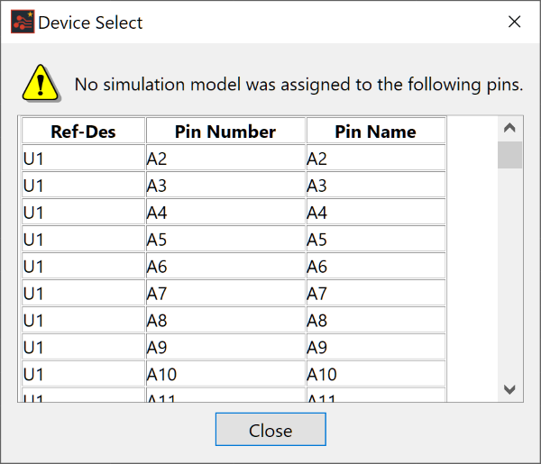
- Click Close in the report dialog to continue.
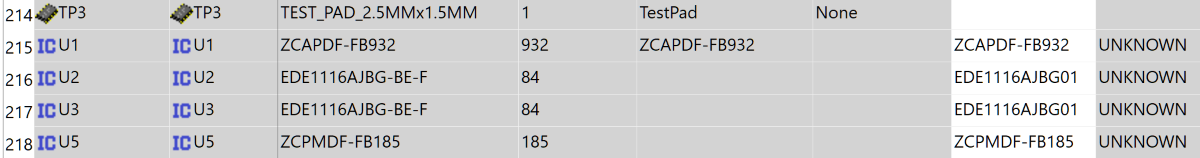
- In the Constraint Browser , click the Devices tab, this shows the devices that are assigned to the Integrated Circuits.
This task is demonstrated in the following video.
