
Task 3: Extracting the Topology
This topic describes how to view the transmission line topology for a signal that is analyzed in Electrical Editor. You can view topologies from either the canvas or from Constraint Browser.
Executing the View Topology Command from the Canvas
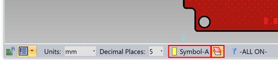
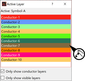
- On the eCADSTAR PCB EditorStatus Bar, click the Active layer. The Active Layer dialog is displayed.
- In the Active Layer dialog, ensure that Only show conductor layers is selected and Only show visible layers is deselected.
- Select the Conductor-7 layer.
- Deselect the Select Only Active Layers button, next to the indicated active layer. The canvas display is updated to also show Conductor-7.
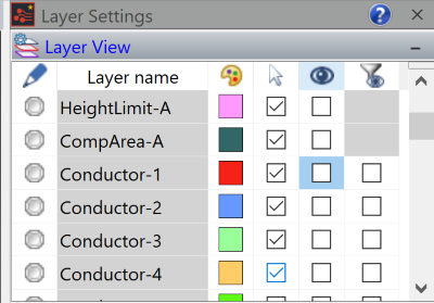
- Turn off the display of Conductor-1
by deselecting the check box in the
 column in
the Layer Settings panel.
column in
the Layer Settings panel.
The Layer Settings panel is displayed by clicking View > Display > Layer Settings on the main menu.
- Zoom in to the area shown in the image below.
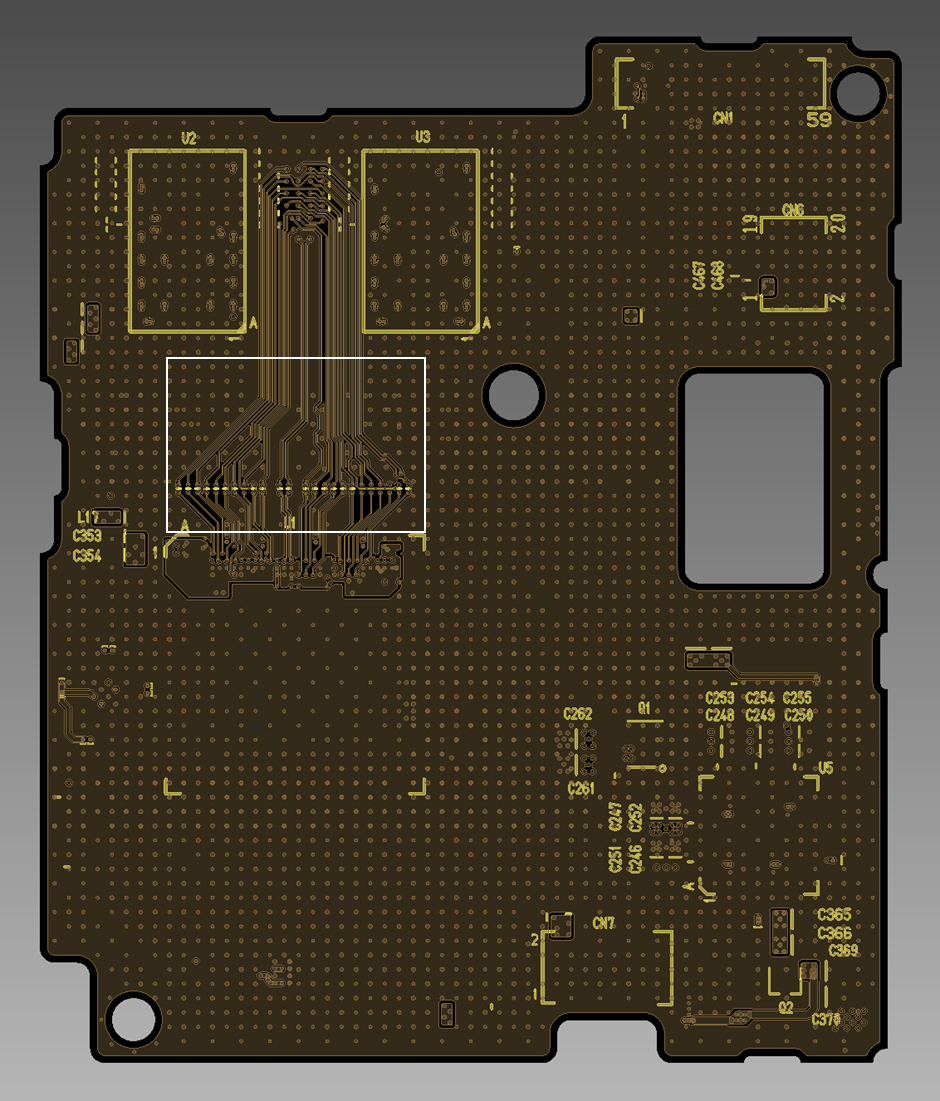
- On the canvas, select the differential pair signal to be analyzed. Select a single segment, or use Shift+Click to select multiple items.
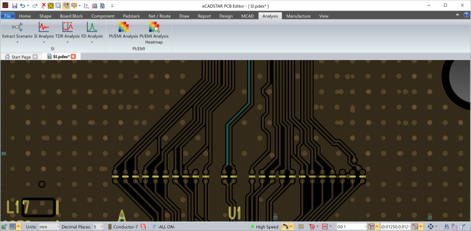
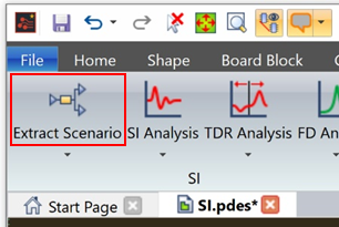
- On the ribbon, click Analysis > SI > Extract Scenario. The selection is extended to include the entire differential pair signal.
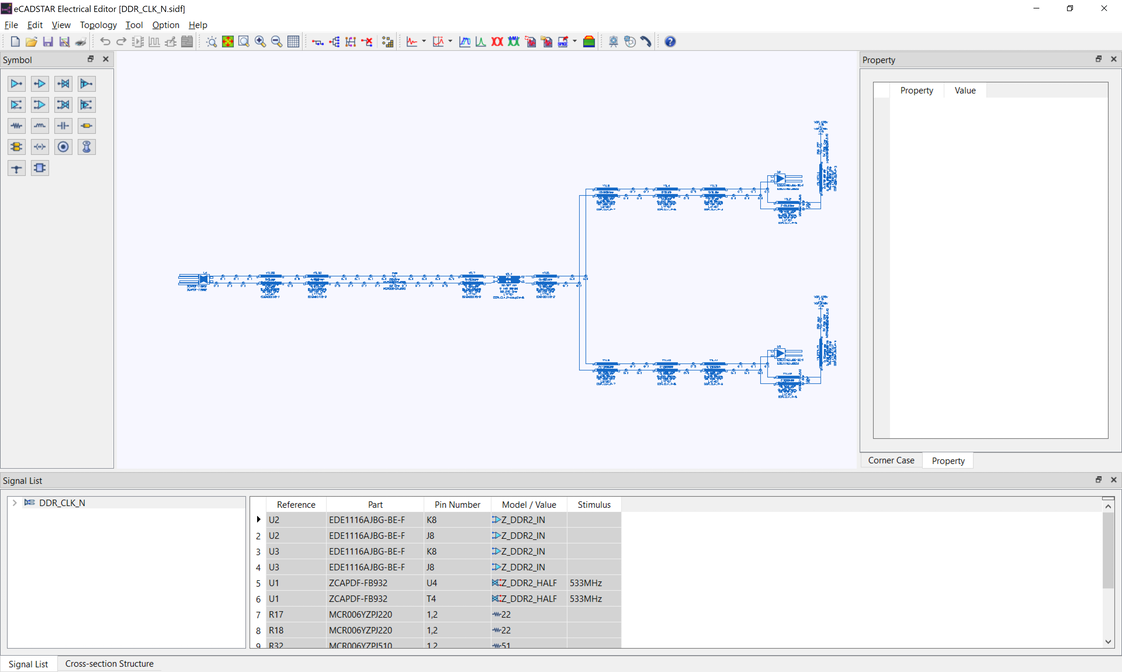
- eCADSTAR Electrical Editor is launched, and displays the transmission line topology for the differential pair signal.
- Select File > Exit to close eCADSTAR Electrical Editor.
Executing the View Topology Command from Constraint Browser
- In Constraint Browser, select the Signals button.
- Deselect
 E-net,
  Power/Ground
and
Power/Ground
and  Bus, and
select
Bus, and
select  Differential
Pairs only. Only the differential pair signals are listed.
Differential
Pairs only. Only the differential pair signals are listed.
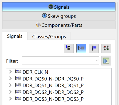
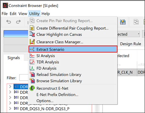
- Select the differential pair signal "DDR_CLK_N" in the tree.
- On the menu bar, click Utility > Extract Scenario.
eCADSTAR Electrical Editor is launched, and displays the transmission line topology for the differential pair signal.
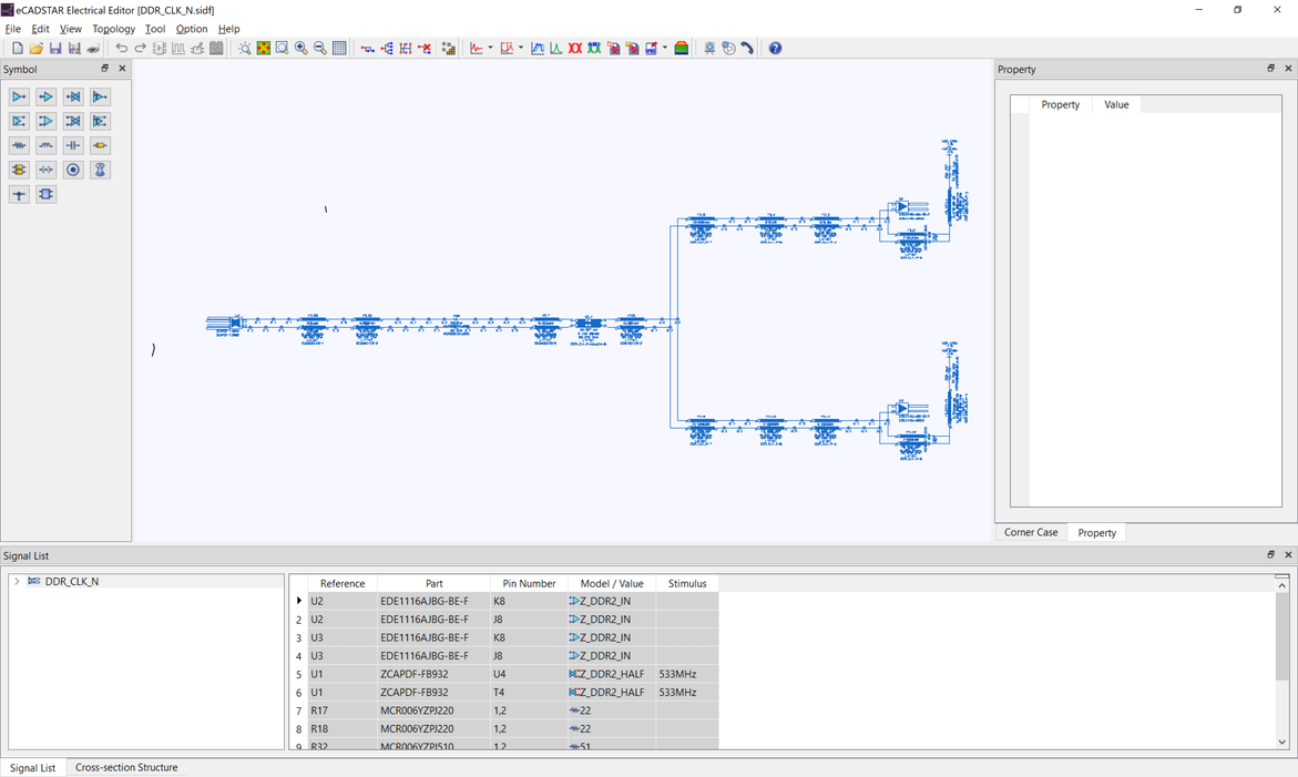
- Select File > Exit to close eCADSTAR Electrical Editor.
This task is demonstrated in the following video.
