
Introduction to eCADSTAR SI Analysis
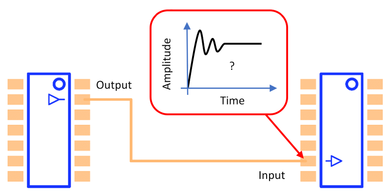
In recent years, low-power, low-voltage digital circuits have become increasingly popular. In high-speed digital signals between integrated circuits, reflection-induced ringing noise caused by an impedance mismatch along the transmission lines can make normal logic switching difficult. This can lead to device malfunction.
The Signal Integrity Analysis feature in eCADSTAR allows you to solve these issues. It provides an effective design environment in which iterations following trial production are reduced, by allowing you to examine Signal Integrity at the board design stage.
Signal Integrity refers to the quality of a signal, and is used to determine whether a receiver correctly detects a signal sent from a driver. It is abbreviated as "SI" in the remainder of this documentation.
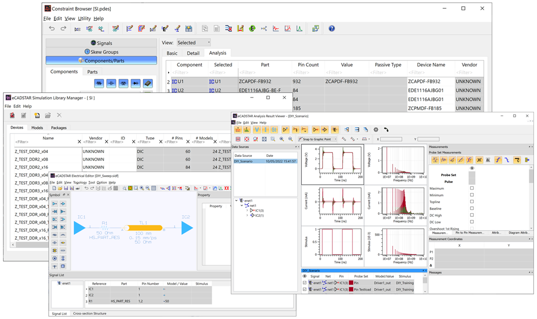
SI Analysis Tools
- Simulation Library Manager: manages models used for SI analyses.
- Constraint Browser: manages net and component information.
- Electrical Editor: displays routing topology for a signal. You can also create a circuit topology and perform "What-if" analysis.
- Analysis Result Viewer: displays the resulting waveforms.
Transmission Line Simulator
eCADSTAR Transmission Line Simulator allows you to analyze temporal variation in a signal flowing through tracks on a printed circuit board. When simulation is performed, a buffer model (IBIS model) is assigned to the device data. An electromagnetic field analysis tool (field solver) models a transmission line that is based on the design data. The elements required for analysis are shown in the following image.
| IBIS Models | eCADSTAR | IBIS Models |
|---|---|---|
|
Electrical information inside the IC.
|
Information about transmission lines.
Other information
|
Electrical Information inside IC.
|
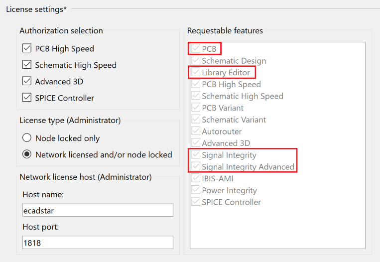
A license for eCADSTAR PCB Editor, Library Editor, Signal Integrity and Signal Integrity Advanced features are required to run this training. Check this as follows:
- On the eCADSTAR PCB Editor ribbon, click File > Configuration > Product Settings. The Product Settings dialog is displayed.
- In the Product Settings dialog, select License Settings. The licensed features for the eCADSTAR items are displayed in the Requestable features box. This is illustrated below.
Training Files
The following training files are provided.
- Schematic: SI.sdes. This is the completed schematic of the SI Training design.
- PCB: SI.pdes. This is the completed PCB of the SI Training design.
- Library: The complete library, provided for the SI Training design.
- Simulation Library Data: SI_models.ixf. This is an ascii file containing simulation library data for the SI Training design.
Prerequisites
Ensure that the Analysis Module Library is being referenced before commencing with this training document.
Before performing SI analysis of a design, you must import simulation models to the design’s simulation library using Simulation Library Browser. Simulation Library Browser is used to manage the imported models.
Referencing the Analysis Module Library
- On the Start menu, click eCADSTAR [Version] > PCB Editor [Version]. eCADSTAR PCB Editor is launched.
- In the File tab, click Configuration > Product Settings. The Product Settings dialog is displayed.
- Select Library
in the list. Click the
 button
for the Library directory. The Open Library
dialog is displayed.
button
for the Library directory. The Open Library
dialog is displayed. - Browse to the following location and click Select Folder: C:\Users\Public\eCADSTAR\eCADSTAR [Version]\Analysis\Library.
You may be required to restart all eCADSTAR Schematic and PCB applications for this change to take effect.
