
Task 15: Netlist Out (Automatic Voltage Generation)
Automatic Voltage Generation is an available option when outputting a netlist from a schematic design. Instead of using gates to define the power characteristics for the circuit, you can use power symbols. These are recognized as the voltage source when using the Automatic Voltage Generator. They are displayed as Vsim (Part name).
Note
For Global Power and Global Ground symbols, if Part Name is defined as a value, then this is interpolated into the SPICE Controller Manager as the DC Value.
For Global Power and Global Ground symbols, if Part Name is defined as a value, then this is interpolated into the SPICE Controller Manager as the DC Value.
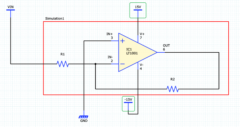
- Continuing with the same design, in the Properties panel, change the Net Name (Part Name) value for the positive supply VCC to "15V" and the negative supply VEE to "-15V".
- On the eCADSTAR ribbon, select the Analysis tab and click Netlist Out. Click Yes when prompted to save the changes. The Netlist Out dialog is displayed.
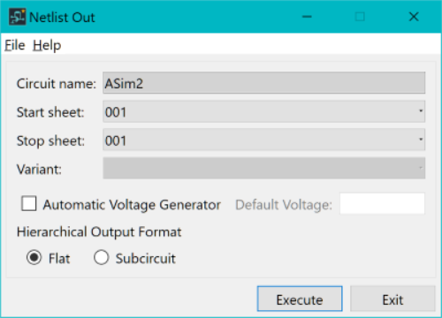
- In the Netlist Out dialog, select Automatic Voltage Generator. Leave the Default Voltage field blank.
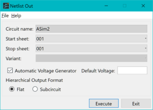
- Click Execute in the Netlist Out dialog to generate the netlist.
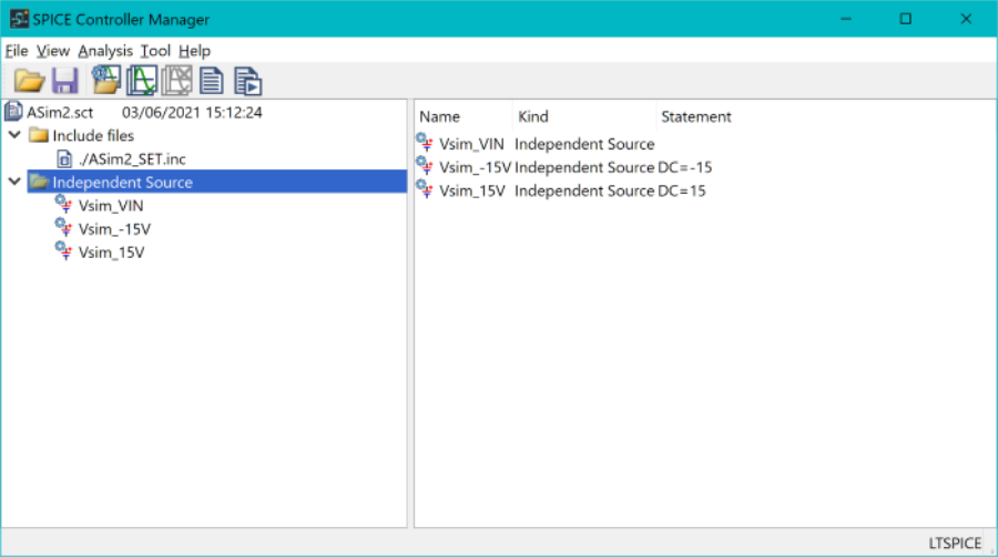
- Click OK in the information dialog to continue. SPICE Controller Manager is displayed. Expand and select the Independent Source branch in the dialog. The DC Value (voltages) are automatically defined for the 15V and -15V signals.
- When simulating the circuit, previous tasks associated with different analysis types can be referenced.
- Close SPICE Controller Manager.
