Frame Netlist Out
The Frame Netlist Out command allows you to output a netlist for a selected simulation frame. This option becomes available when a valid simulation frame is selected on the eCADSTAR Schematic Editor canvas. This creates a netlist for SPICE Controller, but contains only information on items bounded by the simulation frame shape.
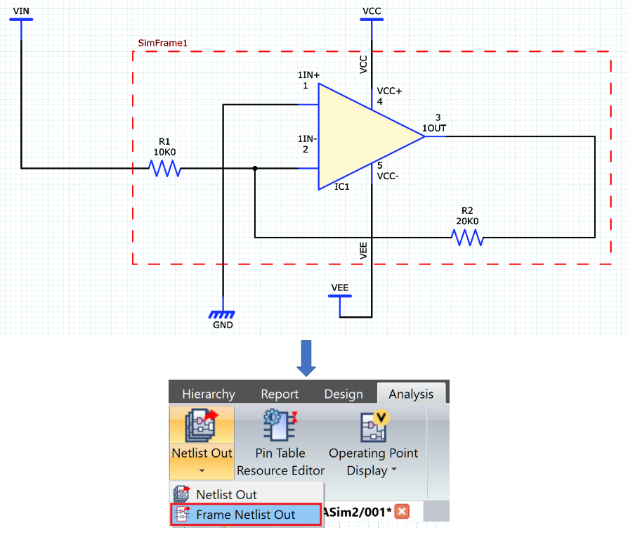
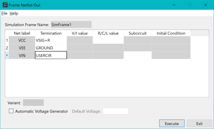
In this example, there are signal lines which exit the simulation frame area. During the Netlist output process, you must define characteristics about those signals to be passed through to the simulator. To can achieve this in the Frame Netlist Out dialog.
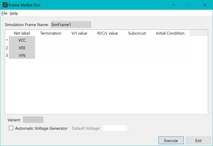
You can define several termination characteristics for each of the signals that exit the simulation frame. The following table describes the termination types that can be defined.
| Termination Type | Termination Description |
|---|---|
| VSIG | Connects the signal source (voltage). |
| VSIG+R | Connects the signal source (voltage) with resistance. Sets the resistance value for the R/C/L values. |
| POWER | Connects the voltage supply. Sets the DC value for the V/I values. |
| POWER+R | Connects the voltage supply with resistance. Sets the DC value for the V/I values. Sets the resistance value for the R/C/L values. |
| ISIG | Connects the signal source (current). |
| ISIG+R | Connects the signal source (current) with resistance. Sets the resistance value for the R/C/L values. |
| ISOURCE | Connects the current source. Set the DC (A) value for the V/I values. |
| ISOURCE+R | Connects the current source with resistance. Sets the value for DC (A) for the V/I values. Sets the resistance value for the R/C/L values. |
| GROUND | Connects the ground. |
| RLOAD | Connects the resistance + ground. Sets the resistance value for the R/C/L values. |
| CLOAD | Connects the capacitor + ground. Sets the value for the capacitor for the R/C/L values. Set any value for the initial voltage for the IC values. |
| LLOAD | Connects the inductor + ground. Sets the value for the inductor for the R/C/L values. Set any value for the initial current for the IC values. |
| OPEN | Connects the resistance with high impedance (100g). |
| NONE | Select this if termination is not required. |
| NETLABEL | Specify a label to select the net to connect. Sets the net label for the V/I values. |
| USERCIR | Connects a user-defined (single pin) subcircuit. Sets the subcircuit name for UserSubCkt. |
| VSIG+USERCIR | Connects a (dual pin) subcircuit with voltage supply. Sets the subcircuit name for UserSubCkt. |
When the required Termination type is defined, the row is filtered to indicate the remaining required signal characteristics.