
Task 14: Frame Netlist Out
- On the Start Menu, click eCADSTAR [Version] > Schematic Editor [Version]. eCADSTAR Schematic Editor is launched.
- On the File tab, click Open. Alternatively, click Open on the Home tab. The Open dialog is displayed.
- Browse to the following location and click Open: C:\Users\Public\eCADSTAR\eCADSTAR [Version]\Analysis\SPICE\ASim2\ASim2.sdes.
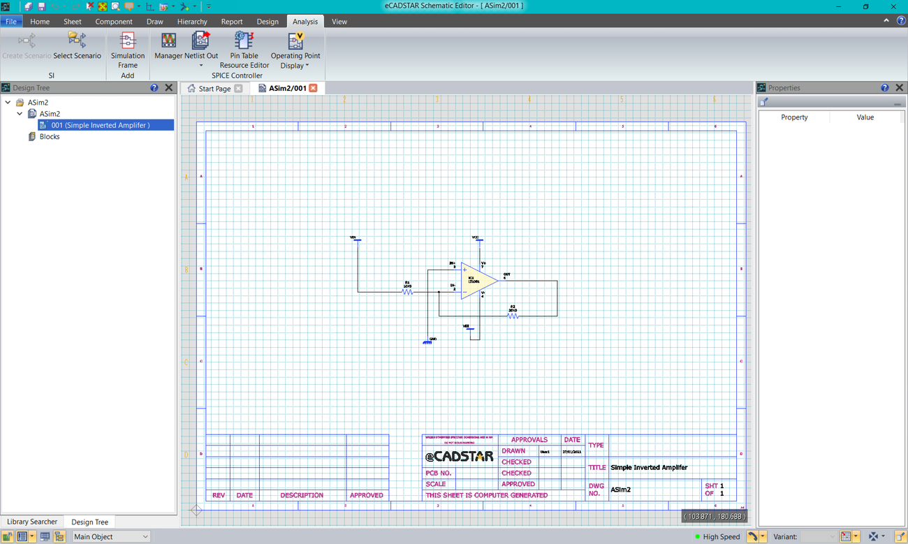
- On the eCADSTAR ribbon, select Add > Simulation Frame on the Analysis tab. The Add Simulation Frame command panel is displayed.
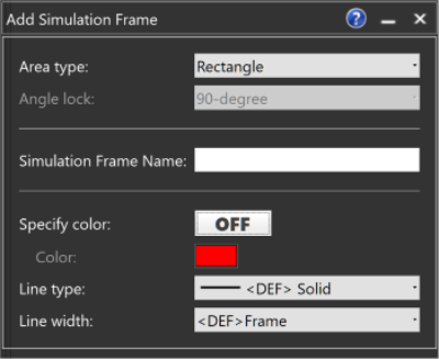
- In the Add Simulation Frame dialog, set the Area Type to Rectangle.
- In the dialog, specify the Simulation Frame Name as "Simulation1".
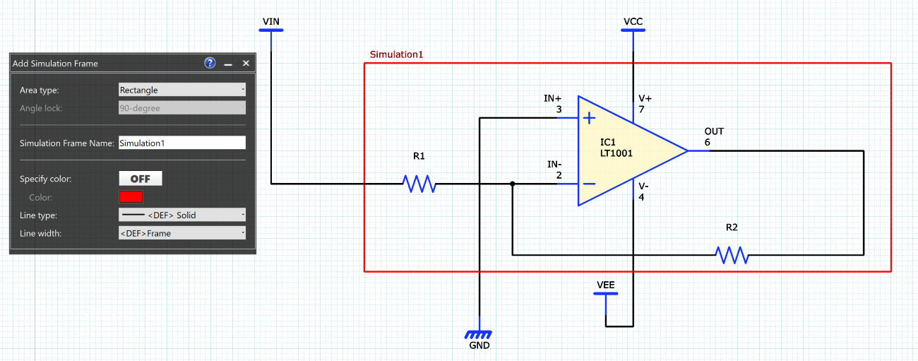
- Draw the simulation frame as shown below. Ensure that the frame intersects the net before the power and ground symbols.
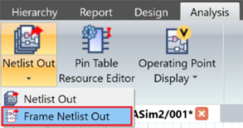
- With the frame selected, click Frame Netlist Out. This is located on the drop-down menu of the Netlist Out command, on the Analysis tab.
- If prompted to save the design because changes have been made, then click Yes to continue.
- The Frame Netlist Out dialog is displayed. This shows the Net Label values for the nets that are intersected by the simulation frame. The characteristics of these signals need resolving before SPICE Controller is launched.
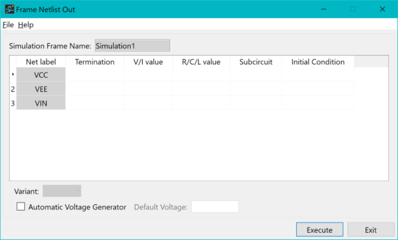
- In the dialog, set the following Termination types and V/I value (voltages) for the signals listed.
| Net label | Termination | V/I value |
|---|---|---|
| VCC | POWER | 15 |
| VEE | POWER | -15 |
| VIN | VSIG | No Value |
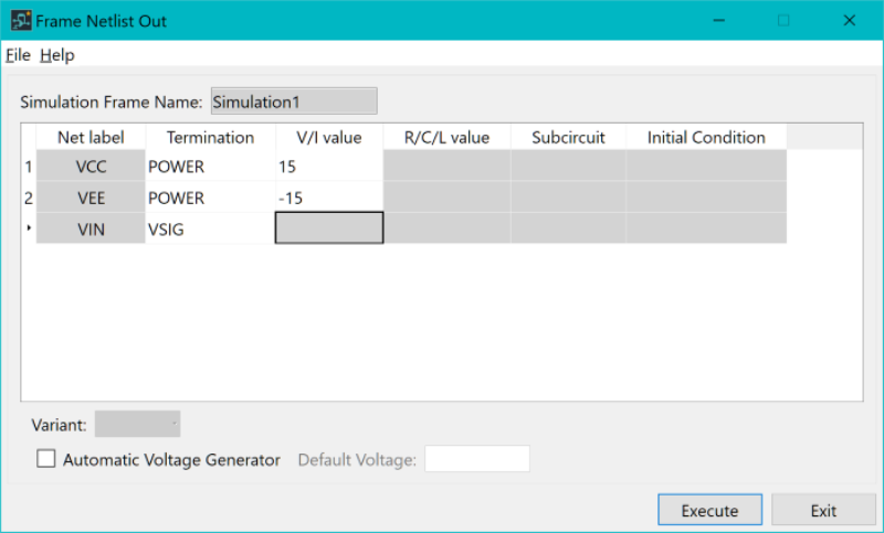
- Click Execute. The Netlist is created.
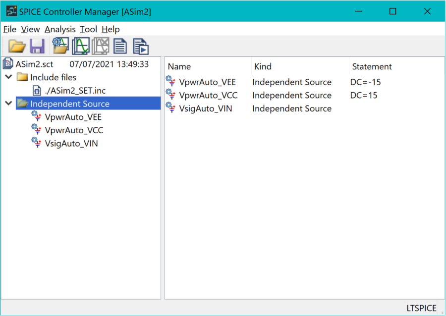
- Click OK in the Information dialog to continue. SPICE Controller Manager dialog is displayed. This contains the data associated with the selected simulation frame.
- Expand the Independent Source item by clicking the arrow to the left.
- Select the Independent Source folder. This displays the definition of the sources.
- When simulating the circuit, previous tasks associated with different analysis types can be referenced.
- Close SPICE Controller Manager.
