
Task 7 (Optional): Creating Variants
In this optional task, you will create design variants. A Design variant uses the same design with different components, which are loaded during PCB assembly according to the selected variation. You can select design variants when manufacturing files and assembly outputs are created. For example, for Bill of Materials, assembly drawings, Pick and Place, photo data, etc.
If you did not complete your version of the entire schematic design as described at the bottom of Task 5, then continue to follow the DIY Training using the following design: C:\Users\Public\eCADSTAR\eCADSTAR [version]\Designs\DIY_Training\SCH\DIY_Training\DIY_Training.sdes.
The Schematic Variant license is required to complete this task in eCADSTAR.
- In eCADSTAR Schematic Editor,
click Component > Variation >
 Manager
on the ribbon. The Variation Manager
dialog is displayed.
Manager
on the ribbon. The Variation Manager
dialog is displayed. - In the Variation Manager dialog, select Simple to create a simple variant group.
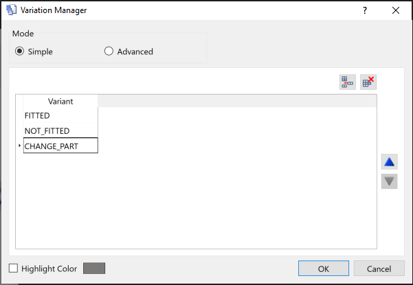
Figure 1: The Variation Manager dialog.
- Add two more variants by clicking
 .
. - Rename the variants by clicking them and typing the following names.
- FITTED
- NOT_FITTED
- CHANGE_PART.
To help identify variant components on the canvas, assign them a specific color using the Highlight Color option.
- Click OK in the Variation Manager dialog, and accept the warning which states that the schematic design will be saved.
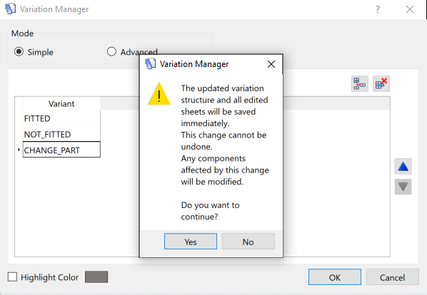
Figure 2: Variation Manager warning message
- Select the connector CN2 on the sheet, and then
click Component > Variant Component
>
 Create. This is now a variant component, and an asterisk is
shown next to the CN2 Reference Designator.
Create. This is now a variant component, and an asterisk is
shown next to the CN2 Reference Designator.
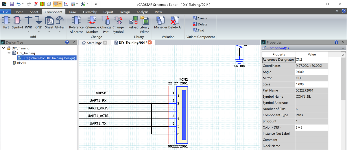
Figure 3: Variant component highlighted on canvas
- Click Home > Browser >
 Component. The Component Browser is launched.
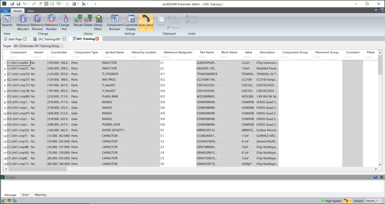
Figure 4: The Component Browser
- In Component Browser, click Home > View > Variants. The Variant View is displayed.
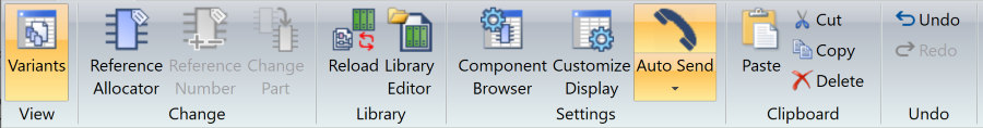
Figure 5: The Component Browser ribbon
- Click Home > Settings > Customize Display on the Component Browser ribbon. The Customize Display dialog is displayed.
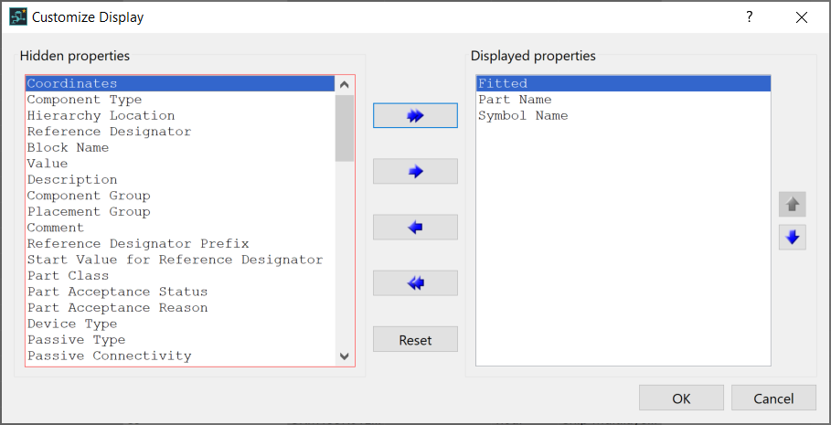
Figure 6: The Customize Display dialog
- Add only the items shown above in the Displayed properties section using the blue arrows, and click OK.
- In the Variant column in Component Browser, right-click and select Sort Descending. The connector CN2 appears at the top of the list as the only variant.
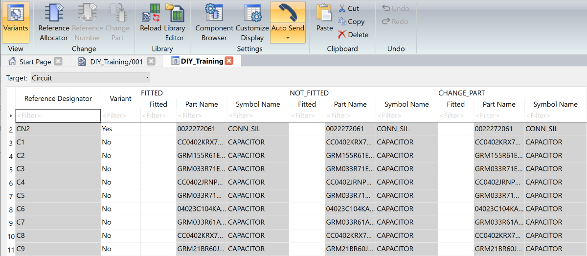
Figure 7: Variation Properties highlighted
- In the Fitted column, specify whether the variant component is fitted by selecting either YES or NO for each variant group. The orange highlighted cells, shown below, indicate that the component is not fitted in the relevant variant group.
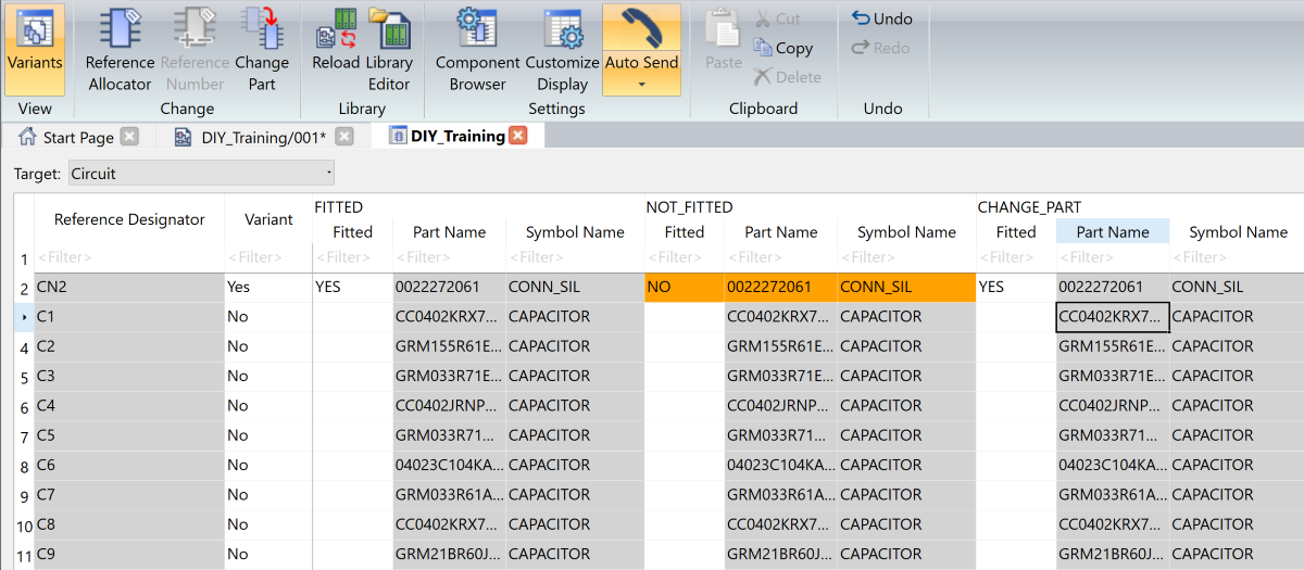
Figure 8: Variant Properties updated
- In the CHANGE_PART variant group, right-click the part name and select Change Part. The Change Part dialog is displayed.
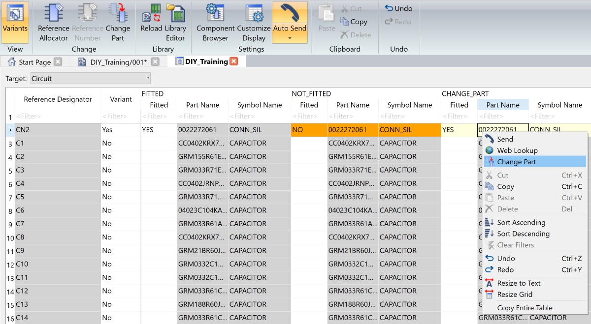
Figure 9: Variant Part set within Constraint Browser
- In the Change Part
dialog, click
 and search for part “0039301060”.
This is an alternate 6-pin connector.
and search for part “0039301060”.
This is an alternate 6-pin connector. - Select this part and click OK in the dialog. This updates the part in Component Browser.
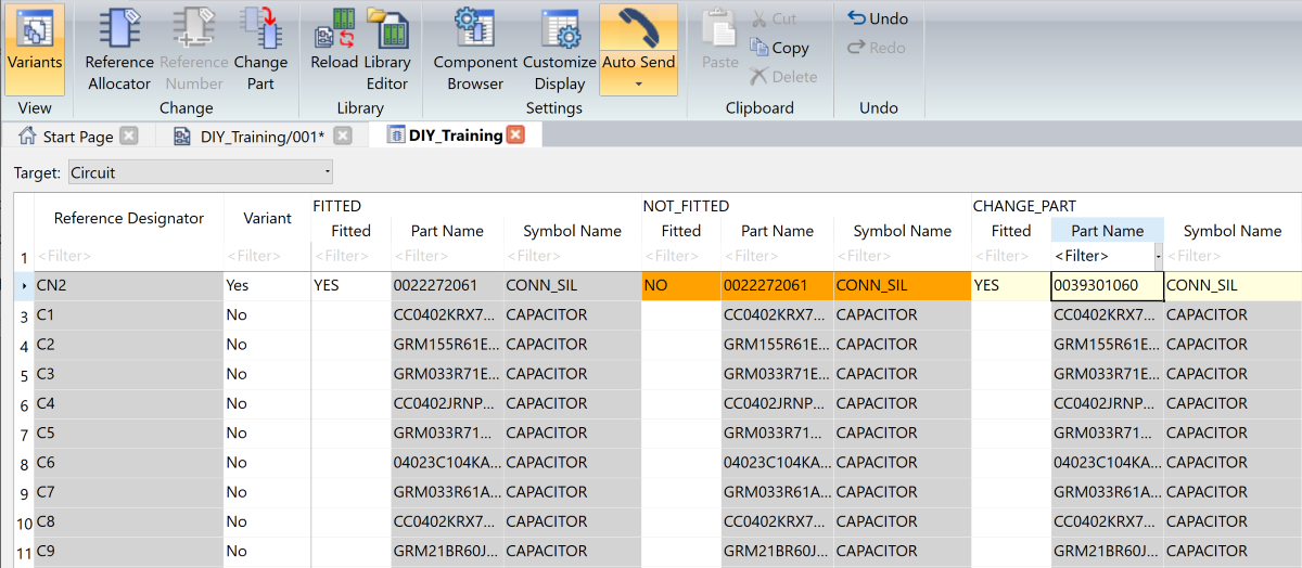
Figure 10: Component Browser variation completed
- Close Component Browser.
- On the status bar in eCADSTAR Schematic Editor, toggle between the variants using the Variant box shown below. Components that are not fitted are shown in gray.
For variant components that are "not fitted", the colors set within the Assignments dialog, Not fitted section override the Highlight Color setting.
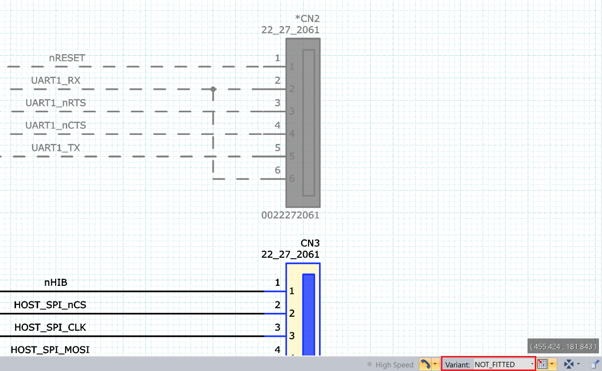
Figure 11: Not fitted items displayed on canvas
- Close the sheet in eCADSTAR Schematic Editor, and save the design to the following location: C:\Users\Public\eCADSTAR\eCADSTAR [version]\Designs\DIY_Training\SCH. Name the design MY_VARIANT_DIY.sdes.
This task is demonstrated in the following video.
