
Task 5: Adding Gates
A gate that is added to a schematic can be a gate in the traditional sense, like an AND gate within a QUAD AND logic device. It can also be a subset of the pinout of a part, such as 2 lanes of PCI Express I/O, within a large Field-Programmable Gate Array (FPGA). This is illustrated below.
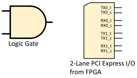
Figure 1: Alternative types of Gate
Refer to Figure 2, below, when completing this task.
- On the eCADSTAR Schematic Editor ribbon, select Home > Add > Part. The Part dialog is displayed.
- In the Part dialog, set Reference: Auto Generate to OFF.
- Set the Reference box to IC6.
- In the Part dialog, click the "..." button by the Part Name box. The Library Searcher panel is displayed.
- In the Library Searcher panel, double-click the part name CD4093BM96. This part symbol is added to the cursor.
- In the Part dialog, set Gate Number to “4” to select the fourth internal gate within this logic device.
- Click the canvas to place the gate on the schematic. Press the Escape key to exit the Add > Part command.
- On the schematic, right-click the gate and select Flip Horizontally on the assist menu.
- On the eCADSTAR Schematic Editor ribbon, select Home > Add > Part. The Part dialog is displayed.
- In the Part dialog, set Reference: Auto Generate to OFF.
- Set the Reference box to R20.
- In the Part dialog, click the "..." button by the Part Name box. The Library Searcher panel is displayed.
- In the Library Searcher panel, double-click the part name CRCW040210K0FKED. This part symbol is added to the cursor.
- Right-click and select Rotate by Specified Angle. The resistor should now be vertical.
- Click on the schematic to place the resistor. Press the Escape key to exit the Add > Part command.
- Copy the GND0V symbol, select a symbol on the canvas and press Ctrl+C.
- Paste the symbol using Ctrl+V. Move the symbol terminal over the bottom terminal of the resistor R20, and click to place on the canvas.
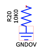
Figure 2: Resistor R20
- Drag the ground symbol downwards away from the resistor. The two symbols are connected.
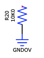
Figure 3: Resistor R20 and Connected Ground Symbol
- On the eCADSTAR Schematic Editor ribbon, click Home > Add > Net.
- On the canvas, connect the components to create the circuit shown below.
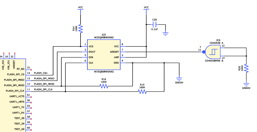
Figure 4: Circuit with Gate Added
- You can continue to complete your own version of the training schematic design now. Alternatively, follow Task 6 to progress through the Schematic training. To complete your own version of the design, refer to the sample schematic design: C:\Users\Public\eCADSTAR\eCADSTAR [version]\Designs\DIY_Training\SCH\DIY_Training\DIY_Training.sdes.
- If you do not complete your own version of the design, then use the sample design provided in Task 6.
The above procedure is demonstrated in the following video.
