
Inputting the Board Outline and Creating Holes, Slots and Shapes
In this section of the training you will enter a board outline, and create associated holes, slots and shapes.
Overview
In the following tasks, you will do the following:
- Choose the appropriate layer.
- Set the required grid.
- If the board outline already exists, for example, the default size that we created in an earlier exercise, this must be deleted before the new one can be created.
- Add the new board outline.
- Enter the layout area.
- Add any required holes and slots
Task 2: Inputting the Board Outline
In this task you will create the shape shown below as a board outline. This replaces the square board outline that you created in Task 1.
-
Either continue using the design MyDesign1.pdes that you created in Task 1, or open the supplied Design1.pdes at the following location: C:\Users\Public\eCADSTAR\eCADSTAR [version]\Designs\DIY_Training\PCB.
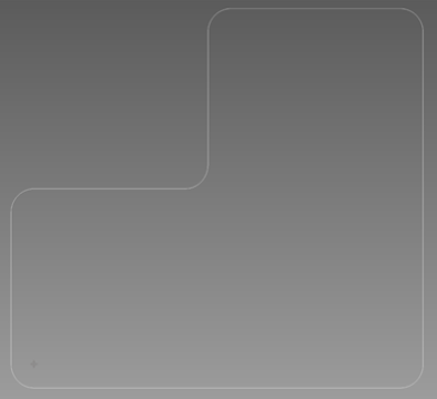
Figure 1: A Typical Board Outline
- Select Canvas View Settings from the Home tab.
- Select the Unit/Background tab, and deselect the Fill board outline check box.
- Close the dialog.
- Set the grid pitch to 0.5mm using the drop-down box.
- Select, and then delete the board outline by pressing the Shift key, and then clicking the edge of the shape to select the whole object.
- Right-click the canvas, and select Delete on the assist menu. Alternatively, press Delete on the keyboard.
- Confirm that the following red shape is now visible on the canvas. This is the layout area.
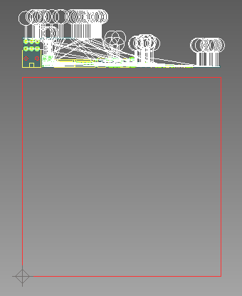
Figure 2: Remaining layout area
- Select the layout area by holding the Shift key, and then clicking the edge of the shape.
- On the Home tab select Delete. Alternatively, press Delete on the keyboard.
- In the Layer Settings panel, set the active layer to Board outline.
- Select the Home tab and click the Polygon button located in the Area Fill group. This will display the Area Fill (Polygon) command dialog as shown below.
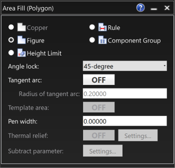
Figure 3: The Area Fill (Polygon) Dialog
Figure is selected by default. If you select an electrical layer, then Copper is automatically selected.
-
Right-click in the canvas to display the assist menu. Click Input Coordinates.
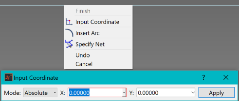
Figure 4: Inputting Coordinates
-
Enter absolute coordinates of X (-5) and Y (-5), and click Apply or press the Enter key.
The shape will only be visible if the cursor is in the canvas area, and not within the Input Coordinates dialog. However, you can safely check on your progress by moving the cursor away from the dialog, and then returning to the dialog to input the next pair of coordinates.
-
Similarly, specify the following coordinates:
- P2 (85, -5)
- P3 (85, 75)
- P4 (38, 75)
- P5 (38, 37)
- P6 (-5, 37)
- Click Finish on the assist menu. The object is entered.
- Close the Input Coordinates dialog, and exit the Add Polygon mode.
- You will now modify the corners of the board outline by applying fillets. Zoom in on the board shape, if required, and click Fillet on the Shape tab.
- Set the parameters in the command dialog as follows: Maximum Radius: 5
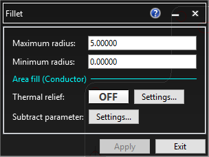
Figure 5: The Fillet Dialog
-
Hold down the Shift key and select the board outline. All of the vertices are now filleted. Press the Esc key to release the selection of the board outline and exit the command. You have now created the board outline.
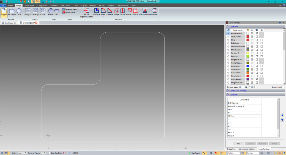
Figure 6: Filleted Board Outline
This task is demonstrated in the following video.
Task 3: Adding the Layout Area
In this task you will add the layout area to the board that you created in Task 2. This provides the section of board that can be used to place components and route tracks within.
- Continue to use the design MyDesign1.pdes or Design1.pdes that you used in Task 2, but do not re-load it.
- In the Layer View panel, set the active layer to Layout Area by selecting the "pencil" icon next to Layout Area.
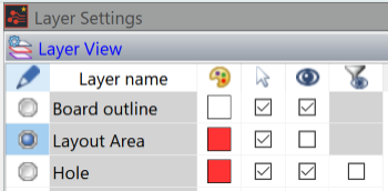
Figure 7: Layer view with Layout Area selection
- In the Shape tab, under Reshape, click Offset.
- Set the parameters in the command dialog as shown below.
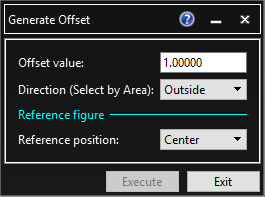
Figure 8: The Offset Dialog
- Select the board outline using Shift+Click, and then click inside the board outline to specify the offset direction.
- On the assist menu, click Exit. The layout area is now added.
- Save the design to the location C:Users/Public/eCADSTAR\eCADSTAR [version]\Designs\DIY_Training\PCB\MyDesign2.pdes. This design will be used again in the next task.
This task is demonstrated in the following video.
You have now added the layout area to the design. In the next task, you will enter some holes.
Task 4: Entering Holes in the Board
In this task, you will add slots and holes to the board. These are often used for mounting purposes and to avoid the PCB fouling onto other components within a product.
- Continue to use the same design as built in Task 3.
- In the Shape tab, click the Round Hole icon. This will open the command dialog.
- Set the Hole diameter to "5.00000" by clicking the Hole diameter box.
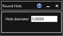
Figure 9: The Round Hole Dialog
- While in this mode, drag the cursor onto the canvas to see the hole attached. Right-click, and select Input Coordinates on the assist menu.
- Enter the following coordinates, and click Apply. The holes will snap to the specified locations.
- (0, 0)
- (80, 0)
- (80, 70)
- (43, 70)
- (0, 32)
- Select Cancel on the assist menu, or press the Esc key.
- In the Shape tab, click the Slot icon.
- Set the parameters in the command dialog as shown below.
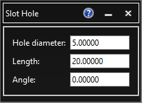
Figure 10: Slot Hole Dialog
- As the hole shape follows the cursor, select Input coordinates on the assist menu. Enter coordinates (61.5, 64.5) and click Apply to snap the slot hole to the location entered.
- Select Cancel on the assist menu, or press the Esc key.
- On the File menu, save the design as C:\Users\Public\eCADSTAR\eCADSTAR [Version]\Designs\DIY_Training\PCB\Mydesign3.pdes. This will be used again later in the course.
This task is demonstrated in the following video.
You have now added holes in the PCB, and have completed all of the board creation tasks. You will move on to component placement in the next section.
