
Display and Environment Settings
You can manipulate your design on-screen to obtain the best possible view. This includes zooming in or out, framing a section of the design, or viewing the complete design. There are many settings that can be adjusted to help in completing the design. The follow information gives guidance on these aspects..
Display Manipulation
Optionally, you can load a color set and display set to match your preference when designing a PCB.
- With a PCB design open:
- On the eCADSTAR PCB Editor ribbon, Design tab, select Import > Layer View, and browse to C:\Users\Public\eCADSTAR\eCADSTAR [version]\Designs\ DIY_Training\PCB\layerview.xml.
- On the eCADSTAR PCB Editor ribbon, Design tab, select Import > Layer Set and browse to C:\Users\Public\eCADSTAR\eCADSTAR [version]\Designs\ DIY_Training\PCB\layerset.xml. In the Import (Layer Set) dialog, click Yes to confirm that layer sets can be overwritten.
- On the Home tab, select Canvas View Settings. Select the Unit/Background tab, and deselect the Fill board outline option. Close the dialog.
- On the view tab, select the Zoom In or Zoom Out icon in order to zoom in and zoom out. Note that the above can also be achieved by using the "+" and "–" keys on the keyboard.
- Click the View All Data icon to view the design. This zooms to show all data outside of the board outline.
- Select the Frame View icon.
- Click and drag from the top-left corner of the design data, and drag down and right as shown below. The selected area is displayed on the canvas.
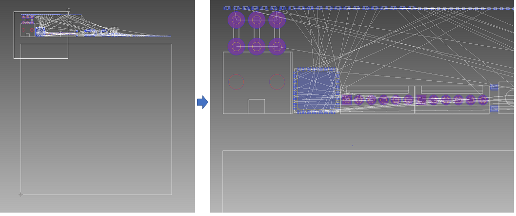
Figure 1: Zoom Area
- Click the View All icon to view the design. This zooms around the board outline only.
- Using the mouse, zoom in and zoom out by pressing the Ctrl key, and scrolling the middle mouse wheel.
- Pan by holding the middle mouse button.
- Alternatively, use the following stroke functions by right-clicking.
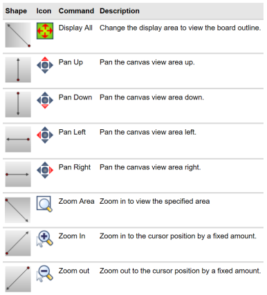
Figure 2: Stroke commands
Default Mouse Settings
There are several ways to drag images, zoom and pan around the screen. The mouse settings are also configurable to your requirements.
- Configure the mouse within the Mouse Settings menu (under File > Configuration > Product Settings > Mouse settings).
- Wheel scroll is configurable.
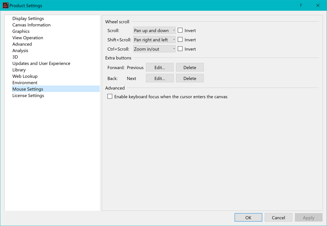
Figure 3: Mouse settings
Storing a view
Any view of the layout on your screen can be stored for later use. This is a useful, time-saving feature that allows you to store an area of the board that you may be working on and return to it when needed.
- Zoom in or out to obtain the section of image that you wish to store.
- From the View tab, click the Save icon as shown. Note that there are 5 available locations in which to store different views. Store the image to the required location.
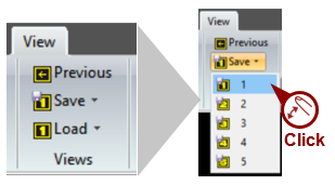
Figure 4: Storing a View
- To re-load the saved image at a later time, click the Load icon.
- 3D views are also available within the View tab. 3D is described in detail later in this document.
Short Cut Keys and Control Keys
eCADSTAR provides a number of short-cut keys and control keys in order to make access to frequently-used functions both easier and faster. You can access the shortcut key list from the File tab.
- In the File tab, select Configuration.
- Click Shortcut Key Settings. A list of the shortcut key settings is displayed.
Setting Grids
Before you enter an object, grid points can be generated on the canvas as a guideline for input. A set of these points is called a "grid".
The grid is a convenient guideline for inputting objects and has the following two roles:
- Show Grid: lattice points are displayed on the canvas as a guideline for input.
- Snap Grid: a grid to which items are accurately placed.
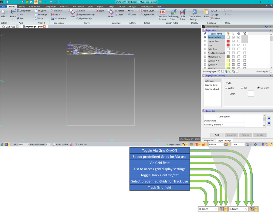
Figure 5: Setting Grids
- Two grid value fields are displayed on the Status Bar for the track grid and via grid.
- Each field is also a pull down list of grid names that are defined within the design rule editor.
- Individual display grids are used for tracks, vias, placement and non-conductive items.
- These grid values and styles are defined in the grid settings dialog.
- Grid values can be typed in the box if pre-defined grids are not listed.
To set a pitch of 0.5mm for the non-conductor grid:
- From the split button on the right of
 Snap
Grid on the status bar, click Grid
Settings. The Grid dialog will
be displayed. If a default grid has already been defined in the
design rule library, its values are displayed. Alternatively, the
user can type in a grid value if required.
Snap
Grid on the status bar, click Grid
Settings. The Grid dialog will
be displayed. If a default grid has already been defined in the
design rule library, its values are displayed. Alternatively, the
user can type in a grid value if required. - To see what is available for predefined grid pitches click the non-conductor cell. The Select Grid dialog is displayed.
- Select the "0.5mm" grid whose X and Y pitches are both 0.5mm, and click OK. This will load grid pitch into the grid dialog.
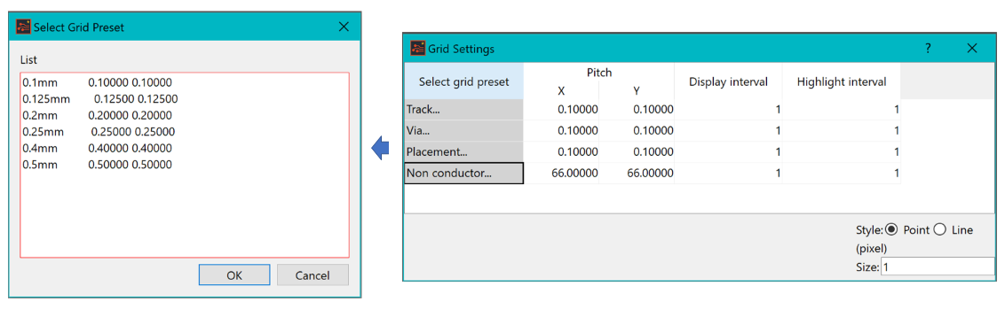
Figure 6: Selecting Grid Pitches
Layer Settings
The Layer Settings panel allows you to select the active layer, along with setting the visible layers, style and selectable layers. The panel consists of the following parts:
- The Layer View, which sets the visibility and color of each layer.
- The Layer Set List: this saves combinations of layer visibility and color.
You can customize the Layer Set List, which is located at the bottom of the Layer Settings menu, as shown below. You can also select the contents of this list, which enables specific design information to be displayed.
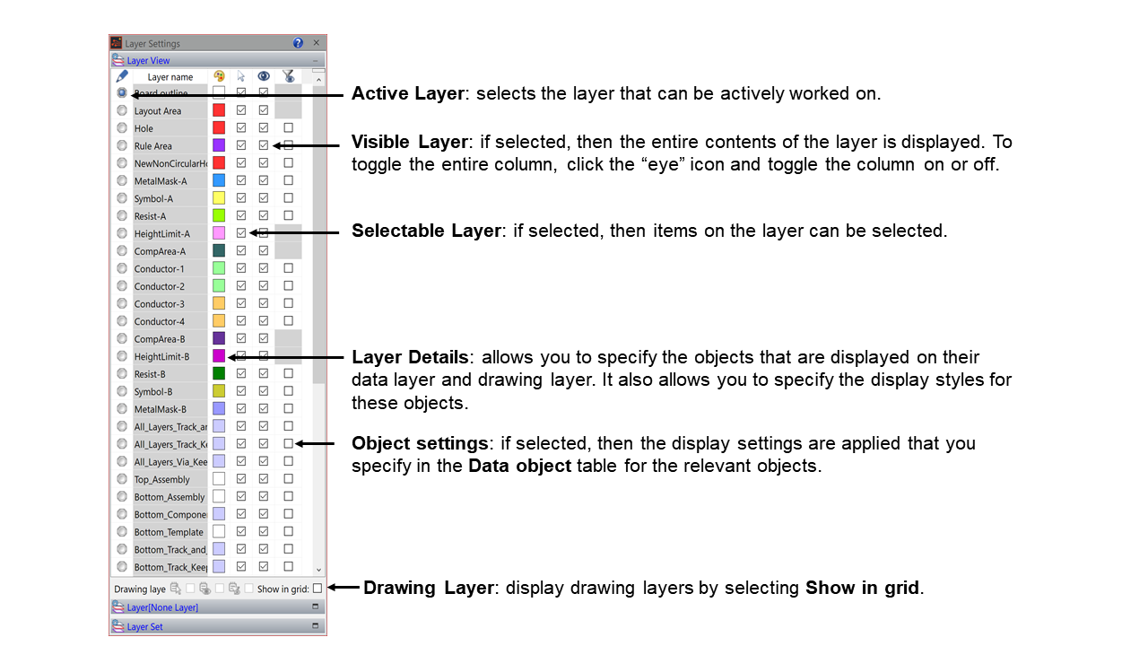
Figure 7: The Layer Set List
If these operations have been followed within eCADSTAR PCB Editor, then it is recommended to close any designs without saving before progressing further with the training.
