
Task 12: Creating Templates on Inner Layers
In this task, you will create templates on the inner layers of the design.
- Open the design Design5.pdes or use your placed and routed design.
- From the Design tab, click Design Settings. The Design Settings dialog is displayed.
- Select the Thermal Relief menu, and set the parameters as shown below. Close the dialog by clicking OK.
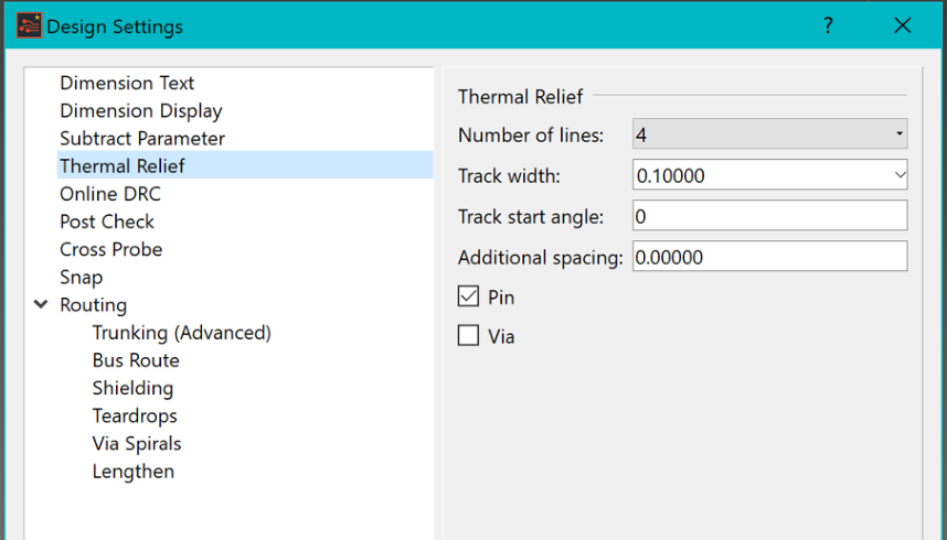
Figure 1: Design Settings
- In the Net/Route tab, click Template Area Settings. The Template Area Settings dialog is displayed. In this dialog you will associate the conductor layers with template layers.
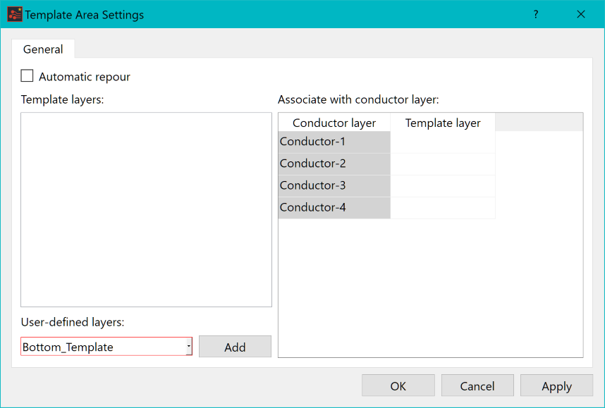
Figure 2: Template Area Settings Dialog
- In the Template Area Settings dialog, ensure that Automatic repour is selected.
- From the User-defined layers pull down list, select Inner_Signal2_Template and click Add. Repeat for the Inner_Signal3_Template, Top_Template and Bottom_Template layers. This makes these layers eligible for template layer usage. This step can be skipped if using supplied design Design5.pdes.
- In the Associate with conductor layer section, for each of the cells in the Template layer column set:
- Top_Template for Conductor-1
- Inner_Signal2_Template for Conductor-2
- Inner_Signal3_Template for Conductor-3
- Bottom_Template for Conductor-4
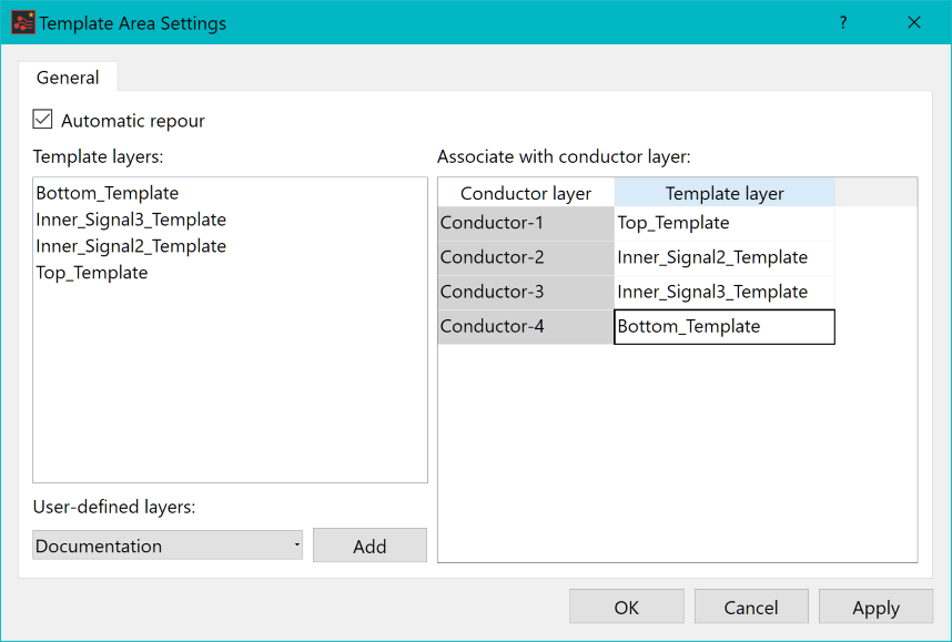
Figure 3: Template Area Settings Dialog (Configured)
- Click OK.
- In the Layer Settings panel, set the active layer to Conductor-2.
- On the Shape tab, select Rectangle from the Area Fill group.
- Set the parameters within the Area Fill Command dialog as shown below.
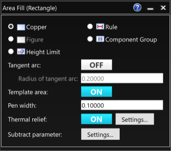
Figure 4: The Area Fill (Rectangle) Dialog
- In the Area Fill (Rectangle) dialog, click Settings by the Subtract parameter field. The Design Settings dialog is displayed.
- In the Design Settings dialog, deselect Allow isolated figure as shown below. This prevents isolated copper from being generated under the fiducials.
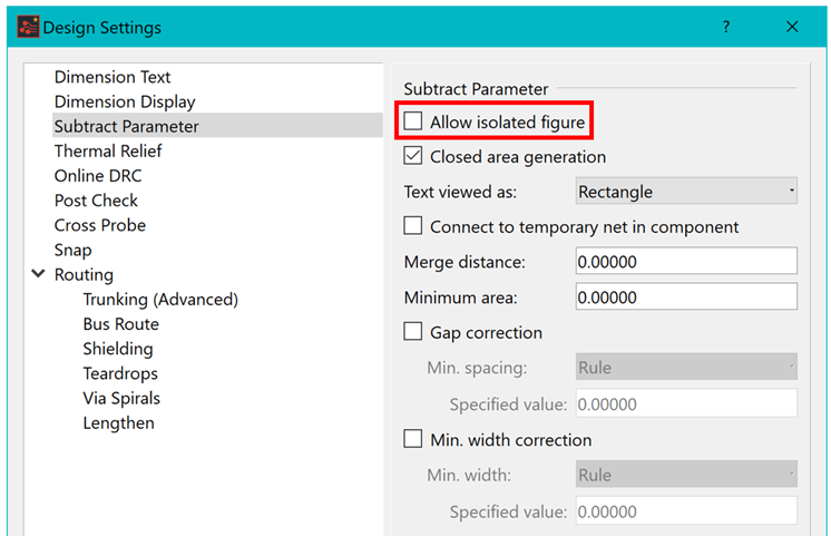
Figure 5: The Design Settings Dialog
- Within the work area, hover the mouse cursor over a GND0V pad and click it. This sets the resulting template to GND0V. You will see that GND0V is now attached to the cursor, and pad and vias associated with GND0V are highlighted.
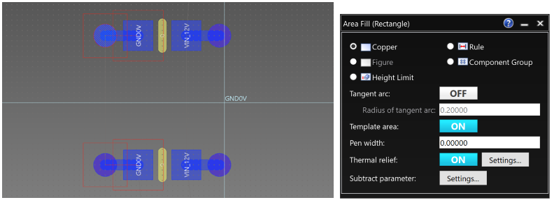
Figure 6: Setting the Template
- Click outside the bottom-left edge of the board, and drag the cursor across the board. Click again when outside the top-right edge. The template copper is poured as shown below.
The dashed outline is the template shape added to the associated template layer.
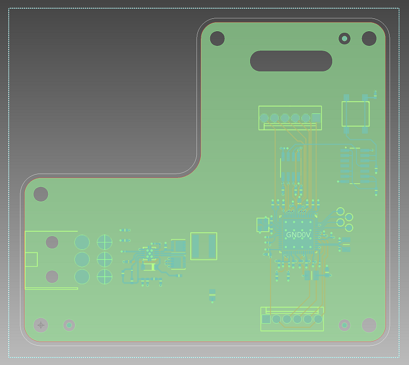
Figure 7: Copper Pour
- Should the template need to be re-poured, Click Generate All from the Generate/Delete Conductor Area button within Net / Route tab.
- Repeat the above template creation process to create the VCC template for the power layer on Conductor-3. If you need to clear the template, select the required conductor layer check box from the Generate /Delete Conductor Area > Each Layer dialog, and click Delete.
This task is demonstrated in the following video.
You have now created inner layer templates.
