
Task 9: Creating a Part
In this task, the pads, padstacks, footprints and symbols that you created earlier in the course will be used to build up the finished parts. These include a Small Outline Integrated Circuit (SOIC) and a Plated Through-Hole (PTH) connector. So far, you have built the following:
Items Created for the NAND Integrated Circuit (IC) CD4093BM96
- Pads: DIY-r207_66 and DIY-r227_86
- Padstack: DIY-r207_66m227_86
- Footprint: DIY_SO14
- Symbol: DIY-NAND
Items Created for the Through-Hole Connector
- Pads: DIY-c200, DIY-c220 and DIY-tc200
- Padstack: DIY-c200h120m220
- Footprint: DIY_CONN6
- Symbol: DIY-CONN_SIL (if created)
Building the NAND Integrated Circuit (IC) CD4093BM96
The following procedure describes how to build the Surface-mount technology (SMT) NAND gate:
- In eCADSTAR Library Editor, select the Parts tab.
- On the eCADSTAR Library Editor ribbon, click Home > Rows > Add. A new row, named "NewPart-1" is added in the Parts tab.
- In the Parts tab, click NewPart-1, and change its name to "DIY-CD4093BM96".
- Right-click DIY-CD4093BM96, and select Edit Part on the assist menu.
- In the displayed Warning dialog, click Yes
- In Part Editor, Detail tab, select IC in the Reference Designator Prefix box.
- Select Integrated Circuit in the Part Class box.
- Enter "2-Input NAND" in the Description box.
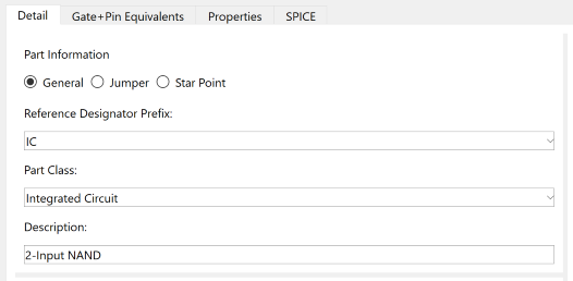
Figure 1: Adding Part Information
- In the Footprint table, click the "..." button in the Name column. This will open the Library Searcher panel.
- Locate and select DIY_SO14,
and click
 in the Library
Searcher panel. The Footprint grid
is updated with the footprint details.
in the Library
Searcher panel. The Footprint grid
is updated with the footprint details.
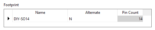
Figure 2: The Footprint Table
- In the Symbols section, enter "5" in the Gate Count box.
- In row 1 of the Symbols table, click the "..." button in the Name column.
- Select DIY-NAND,
and click in the Library
Searcher panel.
- In the Symbols table, copy the row for Gate 1 by clicking in the Name column, and pressing Ctrl+C.
- Select the rows for Gate 2, Gate 3 and Gate 4 by dragging the cursor in the Name column, and press Ctrl+V. The first four gates are set to DIY-NAND.
- For Gate 5, click the "..." button in the Name column and select POWER_GATE.
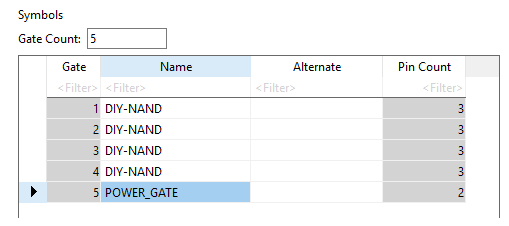
Figure 3: Setting the Symbols Menu
If alternate symbols are available they can be selected by using the combo box list available within the Alternate column cells.
- Set the pin types in the Pin Assignment table, as shown below.
The table can be edited by typing in the required data. However, it is also possible to use the Home > Pins > Assign command to map the gate or symbol pins to the Footprint Pins as a semi-automatic process.
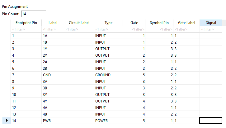
Figure 4: Setting the Pin Types
- In Part Editor, select the Properties tab.
- In the System Part Attributes section, Value column, enter "CD4093BM96" in the Value row.
- On the Part Editor ribbon, select File > Save to save the part. You have now built a Surface Mount Technology (SMT) part.
This procedure is demonstrated in the following video.
Building the Through-Hole Connector
- In eCADSTAR Library Editor, select the Parts tab.
- On the eCADSTAR Library Editor ribbon, click Home > Rows > Add. A new row, named "NewPart-1" is added in the Parts tab.
- In the Parts tab, click NewPart-1, and change its name to "DIY-0022272061".
- Right-click DIY-0022272061, and select Edit Part on the assist menu.
- In the displayed Warning dialog, click Yes
- In Part Editor, Detail tab, select CN in the Reference Designator Prefix box.
- Select Connector in the Part Class box.
- Enter "Friction Lock 0.1 Connector" in the Description box.
- In the Footprint table, click the "..." button in the Name column and select DIY_CONN6.
- Click in the Library
Searcher panel.
- In the Symbols section, enter "1" in the Gate Count box.
- In the Symbols table, Name column, click the "..." button and select DIY-CONN_SIL.
- Click in the Library
Searcher panel to enter this value into the row for gate 1.
You can use CONN_SIL if the task has not been completed for the DIY training symbol.
- Update the Pin Assignment grid as shown below. This will ensure that the mapping of the symbol to the footprint in the part is defined.
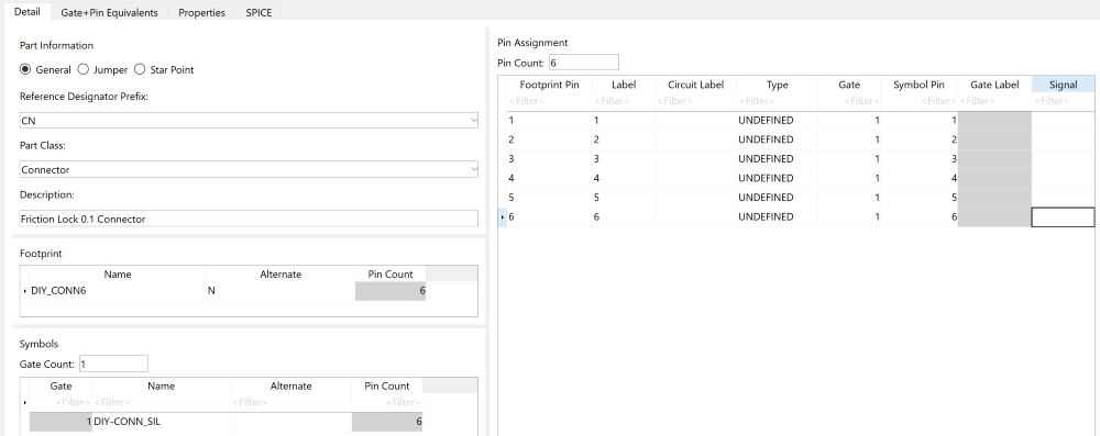
Figure 5: The completed Detail tab of the part
- In Part Editor, select the Properties tab.
- In the System Part Attributes section, Value column, enter "0022272061" in the Value row.
- On the Part Editor ribbon, select File > Save to save to save the part.
This procedure is demonstrated in the following video.
