
Task 7: Constraining Skew Groups
The following procedure describes how to define constraints for Skew Group.
- Using the MyHSDesign1.pdes design from the previous topic, launch Constraint Browser from the Home tab on the ribbon.
- In Constraint browser, select the Skew Groups tab. Confirm that the Skew Groups which you created in the previous topic are displayed.
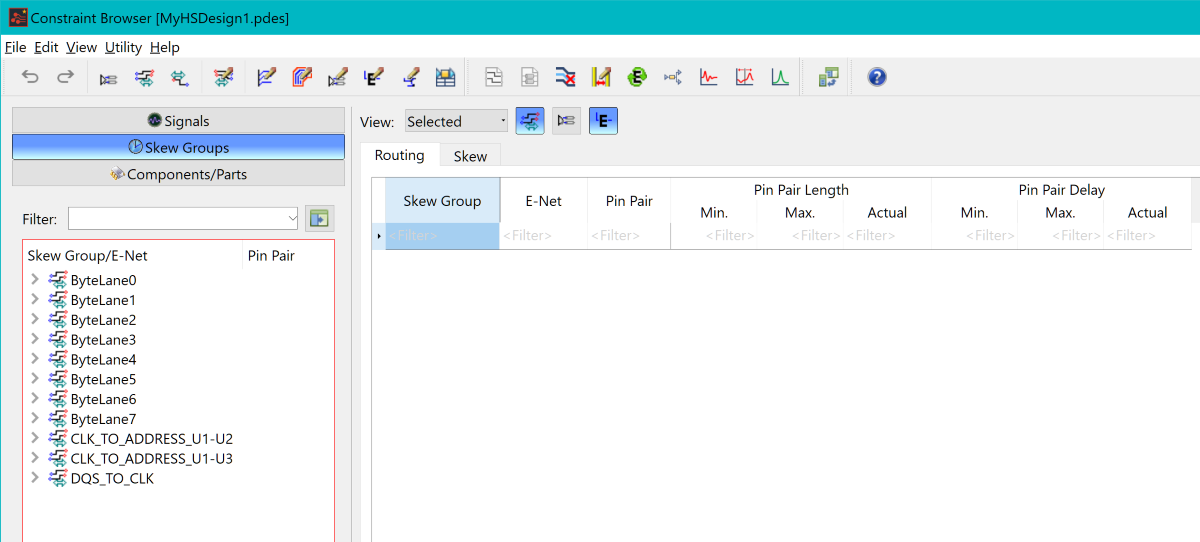
Figure 1: Constraint Browser
- Select the two CLK_TO_ADDRESS skew groups and all the ByteLane skew groups in the list to display them in the table.
- Set the View combo box to Skew Group to simplify the grid.
- In the Routing tab, Pin Pair Length section, set the Max. constraint value to 45mm for all displayed skew groups.
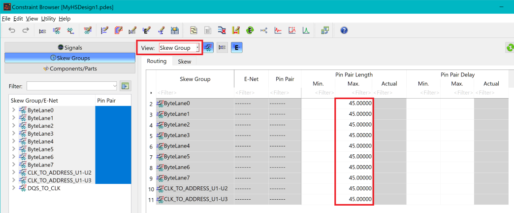
Figure 2: Constraint Browser
Note
It is important to set this value at the top level of the Skew Groups. This ensures that the constraint is applied to all relevant signals. The inheritance of the constraint value onto the Pin Pairs can be viewed by setting the View option to Selected.
- Ensuring that all the Skew Groups are selected,
you will now specify the maximum and minimum difference in length
that is allowed between the Skew Group members. As each Skew Group
has a base signal, the maximum and minimum values are greater or less
than the length of this signal. In this case, the base signal is the
Differential Pair in each Skew Group.
Do this as follows: in the Skew tab in the constraint table, enter these values in the Relative Length Difference section, Min. and Max. columns, for each skew group that you created.
| Skew Group Name | ± Relative Length Difference (Against Base) |
|---|---|
| CLK_TO_ADDRESS_U1-U2 | 1.5 mm |
| CLK_TO_ADDRESS_U1-U3 | 1.5 mm |
| ByteLane0 to ByteLane7 | 1.0 mm |
| DQS_TO_CLK | 1.0 mm |
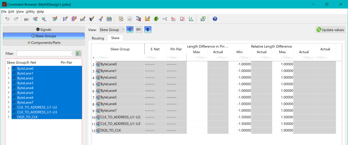
Figure 3: Constraint Browser
- Save the design. In the next task, you will route the signals to topologies.
The above procedure is demonstrated in the following video.
