Understanding Skew Groups
Skew is the difference between the expected arrival time for a signal, and the actual arrival time. In eCADSTAR, you can create skew groups for signals. This allows you to configure the maximum and minimum difference in their arrival times. This is particularly important in high speed designs such as serial communications and memory devices, for example. You can define skew in eCADSTAR using differences in signal length or delay. When using differences in signal length, signals can be matched using the Lengthen command.

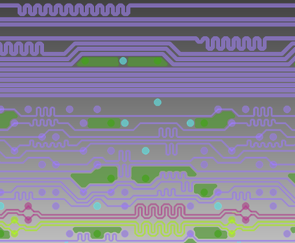
Figure 1: Lengthening Example.
In this DDR2 example, skew groups are needed to define the relationship between the clock signals, buses and data groups. For DDR2 to operate efficiently, specific length constraints must be adhered to. In this task, the following length constraints are defined.
Address to Clock Signals
The Address Bus signals must be routed within ±1.5 mm of the clock differential pair. This ensures that the address signals are received at the memory modules in phase with the clock.
Strobe to Clock Signals
Strobe to Clock dependencies must be defined, and the Strobe to Clock lengths adhered to. In this task, Strobe to Clock skew groups are created with a ±1.0 mm constraint for length difference.
Strobe to Data Lines
The relationship between strobe and data lines must be defined so that they transmit from the controller together, and are received in phase at the memory module. In the example design, the DQ and DQS Skew Group has a ±1.0mm tolerance between the data signals and strobe.

