
Layer Mapping
This page allows you to set up the mapping of layers,
either using CADSTAR layer sub type, plus additional layers to eCADSTAR layers, or all CADSTAR layers
to eCADSTAR layers. Using
layer sub type mapping enhances the migration. This is because the eCADSTAR layers are generated using
the appropriate layer type. See Appendix
C: Cadstar Layer Sub Types for details on the layer mapping of CADSTAR
sub types to eCADSTAR
layers. The following page of the CADSTAR
Migration Mapping dialog is referenced by eCADSTAR
when migrating Library and PCB design data.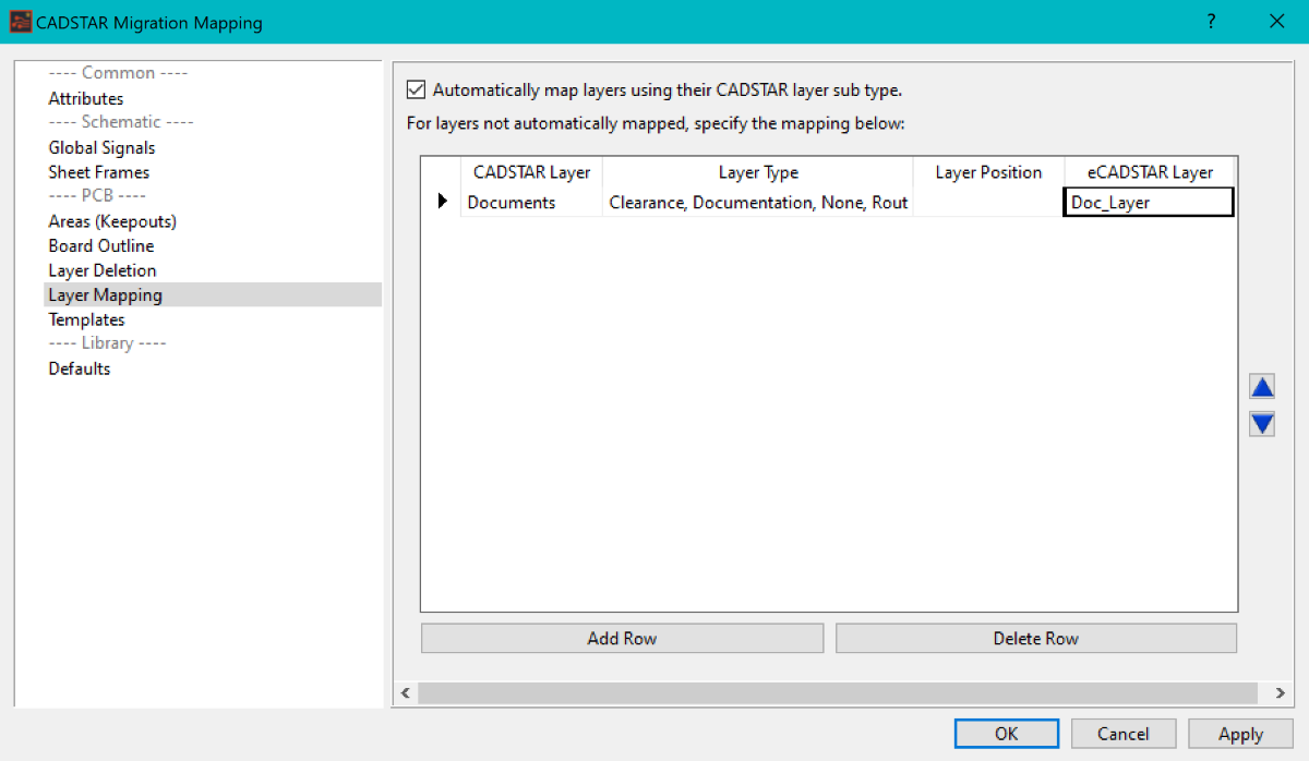
- Layers specified in the mapping file which do not contain data are not migrated into eCADSTAR
- Layer names in eCADSTAR PCB Editor are system reserved against the layer types. Where system layer names are required, the layer mapping interface automatically applies the system layer names. This is shown in the following example.
If you do not map layer names, then the migration process uses the fallback character mapping to ensure that layer names are migrated from CADSTAR to eCADSTAR without invalid characters. This is performed to ensure layer data is not lost during migration. See the Individual Character Mapping and Default Character Mapping documents.
Layer mapping must be considered for full integration. If no mapping is considered, then the resulting library or design cannot easily be synchronized into the full system environment. The migrated data is considered "standalone".
Adding Layer Mapping
- If layer mapping is to include CADSTAR Layer Sub-Types, then you must select the Automatically map layers using their CADSTAR layer sub type option.
Only a single layer with a layer sub type is supported,
per side. For example, if there are two silkscreen layers with layer sub
type of "Silkscreen" associated to the same physical layer,
then only one layer is migrated to eCADSTAR.
Therefore, ensure the pre-migration CADSTAR data only contains one sub-type
per layer. Other Silkscreen layers must have the layer sub type removed
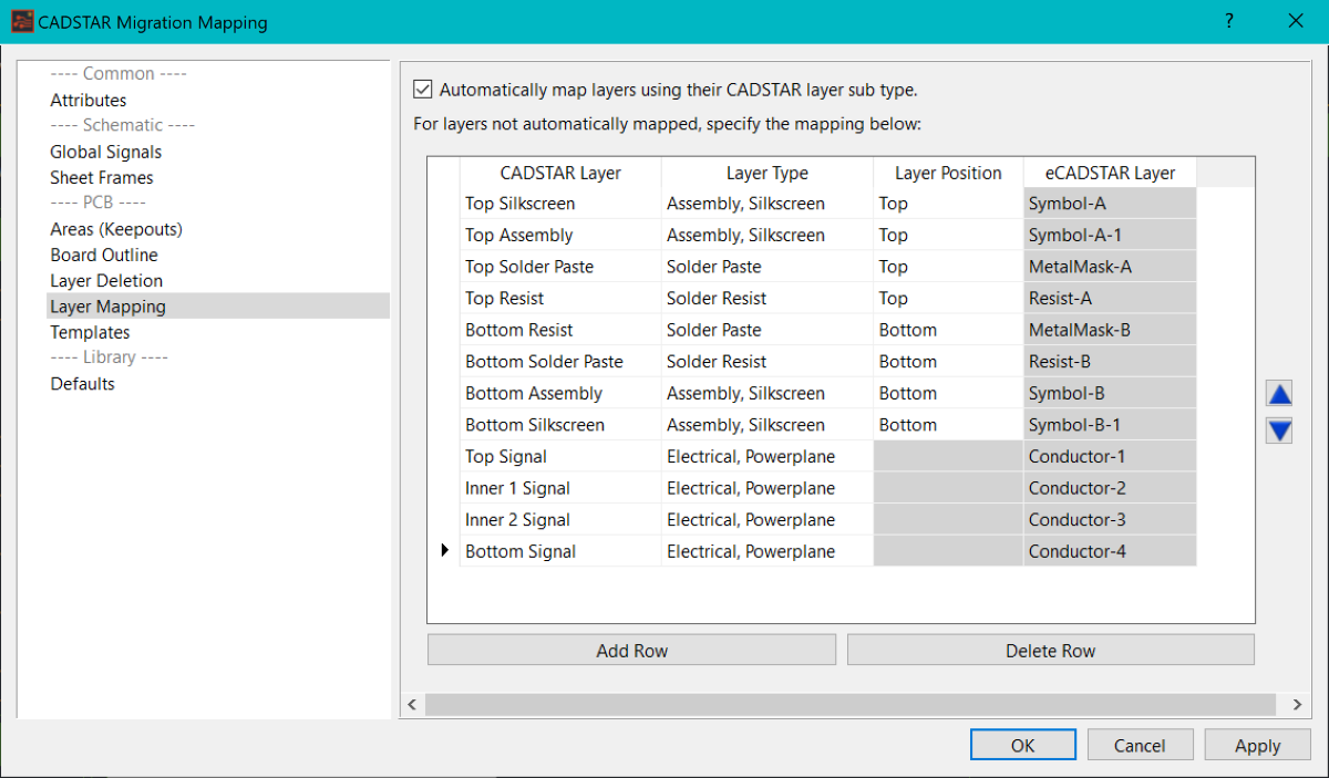
and mapped in the main layer mapping grid. If the Automatically
map layers using their CADSTAR layer sub type option is set in
the mapping dialog and no CADSTAR Layer Sub Types have been set, then
the resulting migrated data will always include the following layers,
by default, and will contain no data from CADSTAR.
| Layer Name | Layer Type |
|---|---|
| Symbol-A | Symbol Mark |
| Symbol-A-1 | Symbol Mark |
| Resist-A | Solder Resist |
| MetalMask-A | Metal Mask |
| CompArea-A | Component Area |
| Symbol-B | Symbol Mark |
| Symbol-B-1 | Symbol Mark |
| Resist-B | Solder Resist |
| MetalMask-B | Metal Mask |
| CompArea-B | Component Area |
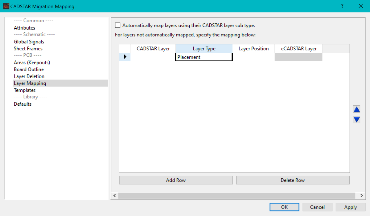
- With the Layer Mapping page of the mapping dialog displayed, click Add Row. A new empty row is added to the grid, and the cell in the CADSTAR Layer is selected for editing. The Layer Type column cell defaults to Placement. Enter a CADSTAR layer which needs to be mapped exclusively (a silkscreen), or beyond the sub type mapping option, for example a second silkscreen.
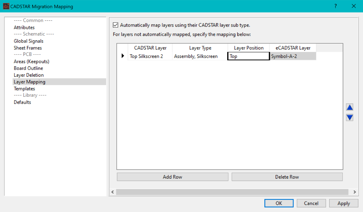
- Change the Layer Type box to represent the layers function.
- Depending on the Layer Type requirement, set the Layer Position box to represent the association to either the Top or Bottom of the board.
-
Click Apply to save the changes and keep the mapping dialog open. Alternatively, click OK to save the changes and close the mapping dialog.
