
CADSTAR Migration Mapping
When migrating a CADSTAR library or design to eCADSTAR, the CADSTAR Migration Mapping dialog allows you to specify the association between the objects in the CADSTAR archive files and the migrated eCADSTAR files. It is launched from the CADSTAR Migration dialog by clicking Edit in the Mapping section. The dialog contains the following sections, which allow you to add relevant settings in the appropriate table: Common, Schematic, PCB and Library.
When migrating data, it is not essential that you configure the contents of this dialog. However, if you add a new row to a table then you must enter all the required data or you cannot save the settings. An error message is displayed if you click OK or Apply in the dialog without specifying these settings.
The mapping for characters is shown in the Individual Character Mapping and Default Character Mapping documents.
Common
Attributes
| Value | Description | |
|---|---|---|
| Mapping table | If you prefer not to map attributes automatically using the migration mapping file, then this section allows you to map the symbol and footprint attributes in CADSTAR to attributes in eCADSTAR. Defining the mapping in this section allows you specify more meaningful attribute names. You can change the order of the rows in this table by double-clicking the header in either column. | |
| CADSTAR Attribute | Specify the name of an CADSTAR attribute, exactly as it appears in CADSTAR. The value that you specify is case-sensitive. | |
| eCADSTAR Attribute | Specify the name of the eCADSTAR attribute to which the associated CADSTAR attribute is mapped. Enter the name exactly as it appears in eCADSTAR. The name that you specify is case-sensitive. | |
| Add Row | Adds a new row below the row that is currently selected in the Mapping table. Alternatively, right-click in the Mapping table and select Add Row on the assist menu. | |
| Delete Row | Deletes the row that is currently selected in the Mapping table. Alternatively, right-click in the Mapping table and select Delete Row on the assist menu. You can delete multiple rows by selecting them using the Ctrl or Shift keys, or by dragging the cursor. |
Schematic
Global Signals
| Value | Description | |
|---|---|---|
| Global Signals table | Allows you to specify that CADSTAR global signals are migrated to eCADSTAR as either power or ground signals. You can change the order of the rows in this table by double-clicking the header in either column. | |
| Global Signal Alternate Name | Specify the name of a global signal , exactly as it appears in CADSTAR. The name that you specify is case-sensitive. | |
| Type | For the associated global signal, specify whether it is migrated
to eCADSTAR as
a power or ground signal. Rules are defined for power and ground
signals in the Rule Editor
Dialog: Tracks Tab.
|
|
| Add Row | Adds a new row below the row that is currently selected in the Global Signals table. Alternatively, right-click in the Global Signals table and select Add Row on the assist menu. | |
| Delete Row | Deletes the row that is currently selected in the Global Signals table. Alternatively, right-click in the Global Signals table and select Delete Row on the assist menu. You can delete multiple rows by selecting them using the Ctrl or Shift keys, or by dragging the cursor. |
Scaling
| Value | Description | |
|---|---|---|
| Schematic and symbol scaling | During migration, this section allows you to scale schematic designs and symbols in the CADSTAR library. This provides sensibly scaled grids when migrating designs that are based on the imperial system. For example, using a scale factor of 1.57480315 changes the grid from 25 thou in CADSTAR to 1 mm in eCADSTAR. | |
| Scale Factor | Enter the scale factor you want (within range 0.1 to 10.0) to change the scale of schematic designs and symbols during migration. Scale factor would be useful when migrating CADSTAR designs using an imperial measurement, for example thou. Although eCADSTAR is natively defined in metric millimeters, designs can be changed to an imperial scale measurement by changing the scale factor. |
Sheet Frames
| Value | Description | |
|---|---|---|
| Sheet Frames table | Allows you to migrate CADSTAR symbols, footprints or documentation
symbols to eCADSTAR
as schematic sheet frames. These objects are mapped as either
symbols or footprints in eCADSTAR.
You can change the order of the rows in this table by double-clicking
the header in either column Note To migrate a documentation symbol from CADSTAR, it must exist in the CADSTAR design, rather than just in the library. |
|
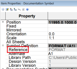
| Reference Name | Specify the reference name for the schematic sheet frame. This
value refers to the Reference
field for the relevant symbol, footprint or documentation symbol
in CADSTAR. This field in the Item Properties
dialog is shown below for a documentation symbol in CADSTAR.
|
|
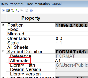
| Alternate Name | Specify the alternate name for the schematic sheet frame. This
value refers to the Alternate field
for the relevant symbol, footprint or documentation symbol in
CADSTAR. This field in the Item Properties
dialog is shown below for a documentation symbol in CADSTAR.
|
|
| Add Row | Adds a new row below the row that is currently selected in the Sheet Frames table. Alternatively, right-click in the Sheet Frames table and select Add Row on the assist menu. | |
| Delete Row | Deletes the row that is currently selected in the Sheet Frames table. Alternatively, right-click in the Sheet Frames table and select Delete Row on the assist menu. You can delete multiple rows by selecting them using the Ctrl or Shift keys, or by dragging the cursor. |
PCB
Areas (Keepouts)
| Value | Description | |
|---|---|---|
| Areas table | Allows you to migrate areas in CADSTAR to specified layers in eCADSTAR. Areas are migrated from CADSTAR as a combination of the area type and its associated layer. You can change the order of the rows in this table by double-clicking the header in each column. | |
| Layer Position | Specify the position of the layer in the CADSTAR layer stack,
or select Top, Bottom
or (All Electrical Layers) to
create a more generic mapping file. This allows it to be used
for more designs. If you specify a layer position, it can then
be selected in this column for other rows.
Note
|
|
| CADSTAR Area Type | Specify the area type for the associated layer number. The
rule areas in CADSTAR are migrated as a combination of the area
type and its associated layer. You can select the following area
types.
|
|
| eCADSTAR Layer | Specify a unique layer in eCADSTAR that the rule area is migrated to. Because each layer in eCADSTAR represents one area type, you cannot map multiple area types to the same layer. Specify the name of the layer exactly as it appears in eCADSTAR. The name that you specify is case-sensitive. | |
| Add Row | Adds a new row below the row that is currently selected in the Areas table. Alternatively, right-click in the Areas table and select Add Row on the assist menu. | |
| Delete Row | Deletes the row that is currently selected in the Areas table. Alternatively, right-click in the Areas table and select Delete Row on the assist menu. You can delete multiple rows by selecting them using the Ctrl or Shift keys, or by dragging the cursor. |
Board Outline
| Value | Description | |
|---|---|---|
| Board Outline | Because board outlines in eCADSTAR have zero width, this section allows you to optionally preserve the line width of a CADSTAR board outline by copying it to a specified eCADSTAR layer. | |
| Copy board outline to another layer (to preserve width) | Allows you to optionally set whether the CADSTAR board outline is copied to a specified layer in order to preserve its width. | |
| Selected | The eCADSTAR Layer box is made available. Specify the eCADSTAR layer which the board outline is copied to. | |
| Not selected | The eCADSTAR Layer box is made unavailable. The CADSTAR board outline is migrated with zero width. | |
| eCADSTAR Layer box | Specify the eCADSTAR layer which the board outline is copied to. You can either enter an existing eCADSTAR later or define a new one. Specify the name of the layer exactly as it appears in eCADSTAR. The name that you specify is case-sensitive. This box is made available when Copy board outline to another layer (to preserve width) is selected. |
Layer Deletion
| Value | Description | |
|---|---|---|
| Layer Deletion table | Unwanted layers that are created during the migration process
can be deleted in this section. This includes CADSTAR construction
layers which are used to migrate layer configuration data to the
dielectric layers in eCADSTAR. Dielectric layers are automatically
placed between each conductor layer in eCADSTAR. Unwanted layers
can either be deleted manually in eCADSTAR,
or deleted automatically during migration by specifying them in
this section. It is recommended to delete them automatically when
migrating multiple designs as it is more efficient. Note
You can specify that layers are either deleted from Footprint Editor, eCADSTAR PCB Editor
or from both applications. Deleting layers from Footprint Editor, for
example, avoids having layers in Footprint Editor
that are not in the design. You can change the order of the rows
in this table by double-clicking the header in either column.When layers are deleted, the resulting library or design will not contain the data associated with the layers. For example, if dielectrics are deleted, then the configuration data for the CADSTAR dielectric layers will not contain this information in eCADSTAR. |
|
| eCADSTAR Layer | Specify any unwanted eCADSTAR layers that are created during the migration process. These layers are automatically deleted from eCADSTAR. Specify the name of the layer exactly as it appears in eCADSTAR. The name that you specify is case-sensitive. | |
| Delete From | Allows you to set whether the associated eCADSTAR
layer is deleted from Footprint Editor,
eCADSTAR PCB Editor
or from both applications.
|
|
| Add Row | Adds a new row below the row that is currently selected in the Layer Deletion table. Alternatively, right-click in the Layer Deletion table and select Add Row on the assist menu. | |
| Delete Row | Deletes the row that is currently selected in the Layer Deletion table. Alternatively, right-click in the Layer Deletion table and select Delete Row on the assist menu. You can delete multiple rows by selecting them using the Ctrl or Shift keys, or by dragging the cursor. |
Layer Mapping
| Value | Description | ||||||||||||||||||||||||||||||||||||||||||||||||||||
|---|---|---|---|---|---|---|---|---|---|---|---|---|---|---|---|---|---|---|---|---|---|---|---|---|---|---|---|---|---|---|---|---|---|---|---|---|---|---|---|---|---|---|---|---|---|---|---|---|---|---|---|---|---|
| Automatically map layers using their CADSTAR layer sub type | If layer sub-types are used in the CADSTAR design, then this check box allows you to automatically map CADSTAR layers to corresponding layers in eCADSTAR, based on the layer sub-type. If layer sub-types are not used, then you can specify the required mapping in the Layer Mapping table. | ||||||||||||||||||||||||||||||||||||||||||||||||||||
| Selected | CADSTAR layers are automatically mapped to corresponding layers
in eCADSTAR, based on the layer sub-type, as shown below. This
is done to resemble the fixed PCB layer names. Layers that are
not mapped automatically can be specified in the Layer
Mapping table. The mapping specified in the Layer
Mapping table overwrites any mapping that is defined in
the mapping file.
|
||||||||||||||||||||||||||||||||||||||||||||||||||||
| Not selected | CADSTAR layers are not mapped automatically to corresponding layers in eCADSTAR, based on the layer sub-type. This setting is recommended if layer sub-types are not used in the CADSTAR design. Define the required mapping by specifying values in the Layer Mapping table. | ||||||||||||||||||||||||||||||||||||||||||||||||||||
| Layer Mapping table |
Allows you to map CADSTAR layers and layer sub-types to specified
layers in eCADSTAR.
Click Note
As some layer names are reserved in eCADSTAR, the following layer naming conventions are recommended. Because the eCADSTAR layers shown below cannot be changed in eCADSTAR PCB Editor, this will allow the layers in the library to match those in eCADSTAR PCB Editor.
|
||||||||||||||||||||||||||||||||||||||||||||||||||||
| CADSTAR Layer | Allows you to specify the CADSTAR layer that is migrated. Either
define this layer by typing a valid alphanumeric value in this
box, or by selecting one of the following values.
|
||||||||||||||||||||||||||||||||||||||||||||||||||||
| Layer Type | Specify the layer sub-type in CADSTAR.
|
||||||||||||||||||||||||||||||||||||||||||||||||||||
| Layer Position | Either specify a numeric value for the layer number, or select
Top or Bottom.
Selecting Top or Bottom
makes the mapping file more generic, which allows it to
be used for migrating more designs. The Layer
Number value represents the conductor layer number in eCADSTAR.
Any gaps between CADSTAR layers are not migrated to eCADSTAR.
For example, if CADSTAR has layers “1, 4, 6, 8”, with gaps between
them, then these layers are mapped to the consecutive layers “1,
2, 3, 4” in eCADSTAR.
|
||||||||||||||||||||||||||||||||||||||||||||||||||||
| eCADSTAR Layer | Specify a valid layer in eCADSTAR that the relevant CADSTAR Layer is migrated to. | ||||||||||||||||||||||||||||||||||||||||||||||||||||
|
|
The row that you select in the Layer Mapping table is moved up by one place in the table. You can select multiple rows using the Ctrl or Shift key, or by dragging the cursor. | ||||||||||||||||||||||||||||||||||||||||||||||||||||
|
|
The row that you select in the Layer Mapping table is moved down by one place in the table. You can select multiple rows using the Ctrl or Shift key, or by dragging the cursor. | ||||||||||||||||||||||||||||||||||||||||||||||||||||
| Add Row | Adds a new row below the row that is currently selected in the Layer Mapping table. Alternatively, right-click in the Layer Mapping table and select Add Row on the assist menu. | ||||||||||||||||||||||||||||||||||||||||||||||||||||
| Delete Row | Deletes the row that is currently selected in the Layer Mapping table. Alternatively, right-click in the Layer Mapping table and select Delete Row on the assist menu. You can delete multiple rows by selecting them using the Ctrl or Shift keys, or by dragging the cursor. |
Templates
| Value | Description | |
|---|---|---|
| Templates table | For each CADSTAR layer that has templates, specify the eCADSTAR layer that it is migrated
to. This is required as each conductor layer in eCADSTAR is defined on a separate
layer. Click |
|
| CADSTAR Layer | Specify a valid CADSTAR layer that has templates. | |
| eCADSTAR Layer | Specify a valid layer in eCADSTAR that the relevant template layer is migrated to. | |
|
|
The row that you select in the Templates table is moved up by one place in the table. You can select multiple rows using the Ctrl or Shift key, or by dragging the cursor. | |
|
|
The row that you select in the Templates table is moved down by one place in the table. You can select multiple rows using the Ctrl or Shift key, or by dragging the cursor. | |
| Add Row | Adds a new row below the row that is currently selected in the Templates table. Alternatively, right-click in the Templates table and select Add Row on the assist menu. | |
| Delete Row | Deletes the row that is currently selected in the Templates table. Alternatively, right-click in the Templates table and select Delete Row on the assist menu. You can delete multiple rows by selecting them using the Ctrl or Shift keys, or by dragging the cursor. |
Library
Defaults
| Value | Description | |
|---|---|---|
| Default thermal relief | Allows you to define the default thermal relief settings for thermal pads. This setting is required for library migration only, as CADSTAR PCB designs contain their own default settings for thermal relief. The values that you specify are used if no values are set in CADSTAR. In eCADSTAR, these values can be specified in the Pad Editor Dialog. | |
| Clearance (mm): | For padstacks that are migrated from a CADSTAR library, specify the default width of the line that forms the shape of the thermal pad. Specify a value between 0 and 12.7mm. | |
| Relief width (mm): | For padstacks that are migrated from a CADSTAR library, specify the default spoke width for thermal pads. Specify a value between 0 and 12.7mm. | |
| Padstacks | Allows you to remove unconnected pads in the board library that are on inner layers. These are shown in the Unconnected pad column in the Padstack Editor Dialog, in eCADSTAR Library Editor. | |
| Suppress unconnected pads on inner layers |
|
| Value | Description |
|---|---|
| OK | If all required values have been entered in the CADSTAR Migration Mapping dialog, then the values are saved, and the dialog is closed. If you add a row to a table in this dialog, then you must specify values for it before the dialog settings are saved. |
| Cancel | The CADSTAR Migration Mapping dialog is closed, without saving your settings. |
| Apply | If all required values have been entered in the CADSTAR Migration Mapping dialog, then the values are saved and the dialog remains open. If you add a row to a table in this dialog, then you must specify values for it before the dialog settings are saved. |
CADSTAR Design Migration
Migrating CADSTAR to eCADSTAR: Introduction
Migrating CADSTAR to eCADSTAR: Getting Started
© Zuken 2021
