
Task 8: Setting the Conductor Clearances
In this task, you will learn how to set conductor clearances. Conductor clearances define the minimum clearances that are required for a design. Multiple clearances can be set for different sections of the design, including inner layer clearances and differential pair clearances, for example. A design rule stack is also defined within this section. You can have many different stacks within your design rule.
Electric Objects
- Select the Conductor Clearance tab, and then select the Conductor tab.
- In the Design rule group section, specify a new design rule of "0.1mm" and click Add. The specified value is added to the Design rule group list.
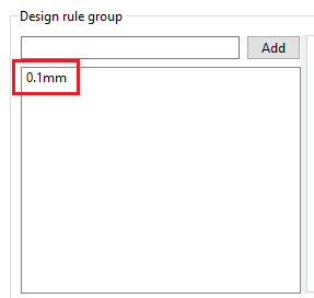
Figure 1: Setting the Design Rule Group
-
In the Basic settings section, enter "0.10000" in the first cell of the Track row, (also the first cell of the Track column).
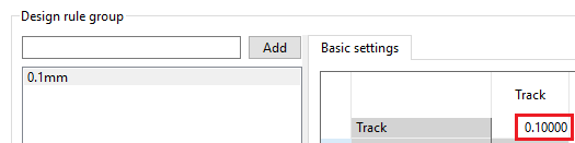
Figure 2: Basic Settings
- Copy the contents of this cell (first cell of the Track row/Track column) by pressing Ctrl+C.
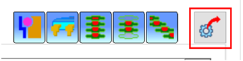
- Display the Basic Settings tab by clicking the Display basic clearance settings dialog button.
- Click the arrow next to the Track row and drag the cursor down to cover the whole of the table. Press Ctrl+V to paste the value "0.10000" into all selected cells.
- Close the Basic settings dialog by clicking X.
- In the Design rule stack section, create an entry of "0.1mm" and click Add. The specified value is added to the Design rule stack list.
- In the Design rule stack section, select 0.1mm for each conductor layer in the Design rule group column. The design rule stack is now ready to use.
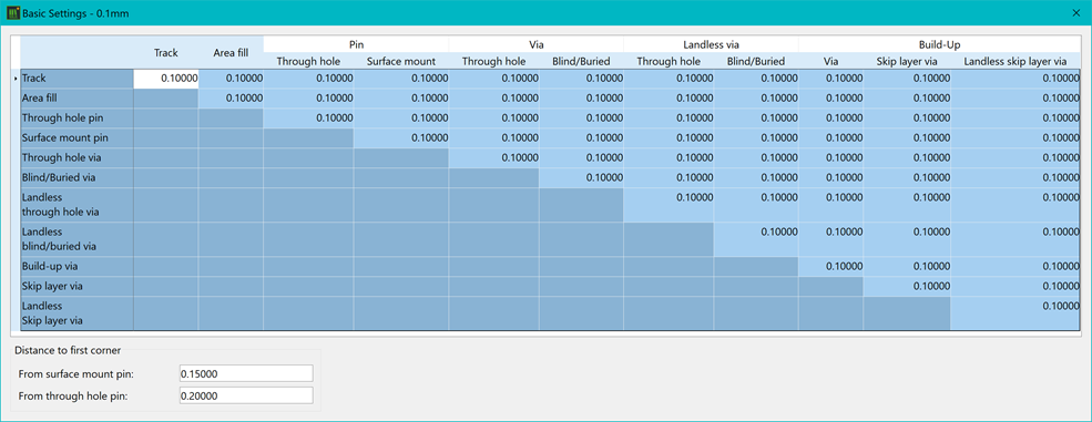
Figure 3: Basic Settings
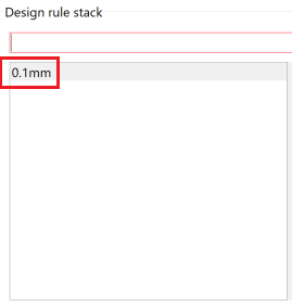
Figure 4: Setting the Design Rule Stack
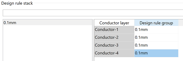
Figure 5: Setting Unit Values for Conductor Layers
- In the Default design rule stack list, set all of the fields to be "0.1mm".
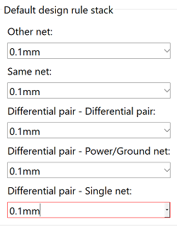
Figure 6: Default design rule stacks
- Now set the distance to first corner. In the Design rule group section, set the Distance to first corner to be ‘0.20000’ for both surface mount and through-hole pins.
These values set the minimum distance a track must be from the edge of a pad before it can turn a corner. This is to prevent acute angles into pads that may cause manufacturing issues with the board.
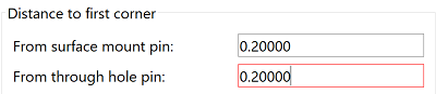
Figure 7: Setting Distance to First Corner
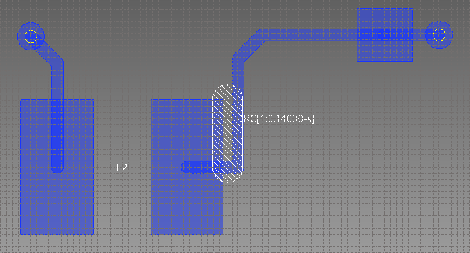
Figure 8: Example of DRC result of routing pattern violating the Distance to First Corner rule
- Click Save. At this
stage, ignore any warnings or errors.
This task is demonstrated in the following video.
