
Task 11: Displaying Delays
Constraint Browser allows you to display the delay between pin pairs. By creating a Skew Group, you can check the difference (skew) of the delay between multiple pin pairs.
- In Constraint Browser, select
 E-net, and enter "DQ" in
the Filter box. Only Differential Pairs
or E-nets whose name includes "DQ" are displayed in the
tree.
E-net, and enter "DQ" in
the Filter box. Only Differential Pairs
or E-nets whose name includes "DQ" are displayed in the
tree.
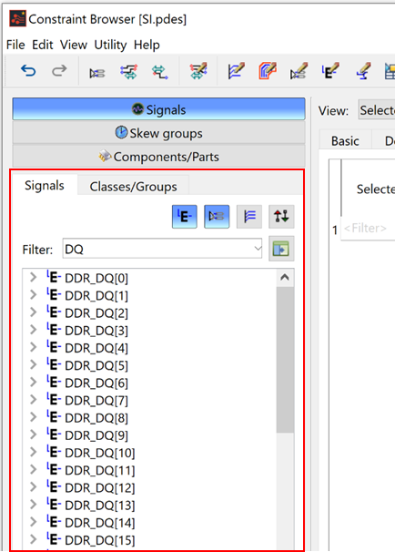
- Select differential pair "DDR_DQS0_N-DDR_DQS0_P" and E-Nets "DDR_DQ[0]" to "DDR_DQ[7]".
- Use the Ctrl key to select multiple rows in the Tree view.
- Right-click to display the assist menu, and select Create Skew Group. The Create Skew Group dialog is displayed.
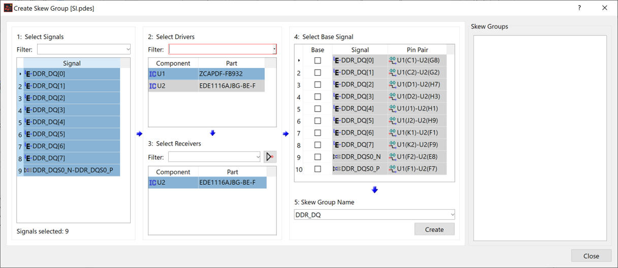
- The selected signals are shown in the 1: Select Signals section. The Drivers and Receivers are pre-determined, and the signals and pin pairs are listed in the 4: Select Base Signal section.
- Select the Base check box for the row containing "DDR_DQS0_N" in the 4: Select Base Signal section. This automatically enables the Base check box for the row containing "DDR_DQS0_P".
- In the 5: Skew GroupName section, "DDR_DQ" is displayed as the initial value. When creating a skew group using multiple E-Nets, the common string for signal names is displayed as the initial value.
- Change the skew group name to "DDR_DQ_1", and click Create.
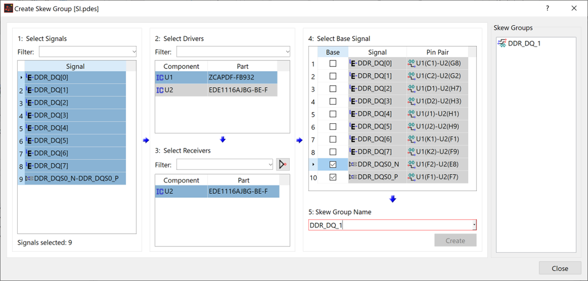
The Skew Group is created, and is shown populated in the Skew Groups section.
- Select Close to close the Create Skew Group dialog.
- In Constraint Browser, select the Skew groups button, and confirm that the created skew group has been added.
- Select the "DDR_DQ_1" skew group in the tree. The pin pairs that belong to the selected skew group are listed in the table.
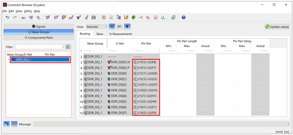
- Select the Skew tab in the table on the right. Scroll the grid to locate the Relative Delay Difference columns.
- Specify the following values in the Min.
and Max. cells in the Relative
Delay Difference group.
Min.: -0.01
Max.: 0.01
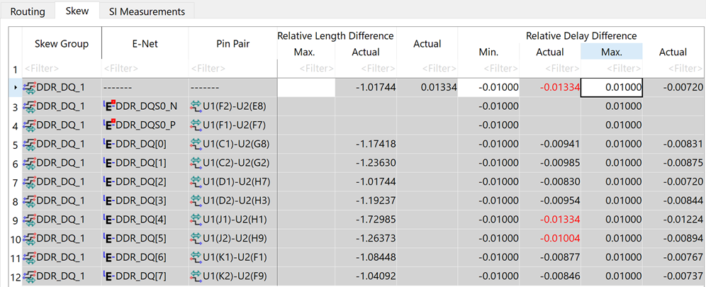
- After Min. and Max. values are added, the results are automatically updated. Optionally, you can click
 Update
values. The measured value, obtained from the routing status
of the board, is shown in the Actual
cells for the pin pairs listed in the table. The value in red indicates
that it violates the preset rule.
Update
values. The measured value, obtained from the routing status
of the board, is shown in the Actual
cells for the pin pairs listed in the table. The value in red indicates
that it violates the preset rule.
This task is demonstrated in the following video.
