
Design Rule Checking and Parts Lists
Design Rule Checks
Design rule checks (DRC) allow you to detect physical problems in a PCB design. You can also check design rules in the schematic, however, these are related to drawing conventions, properties and connectivity. You can specify what is checked in the DRC Settings dialog, shown below. This is displayed by clicking Report > Design Rule Checking > DRC Split button > DRC Settings on the eCADSTAR Schematic Editor ribbon.
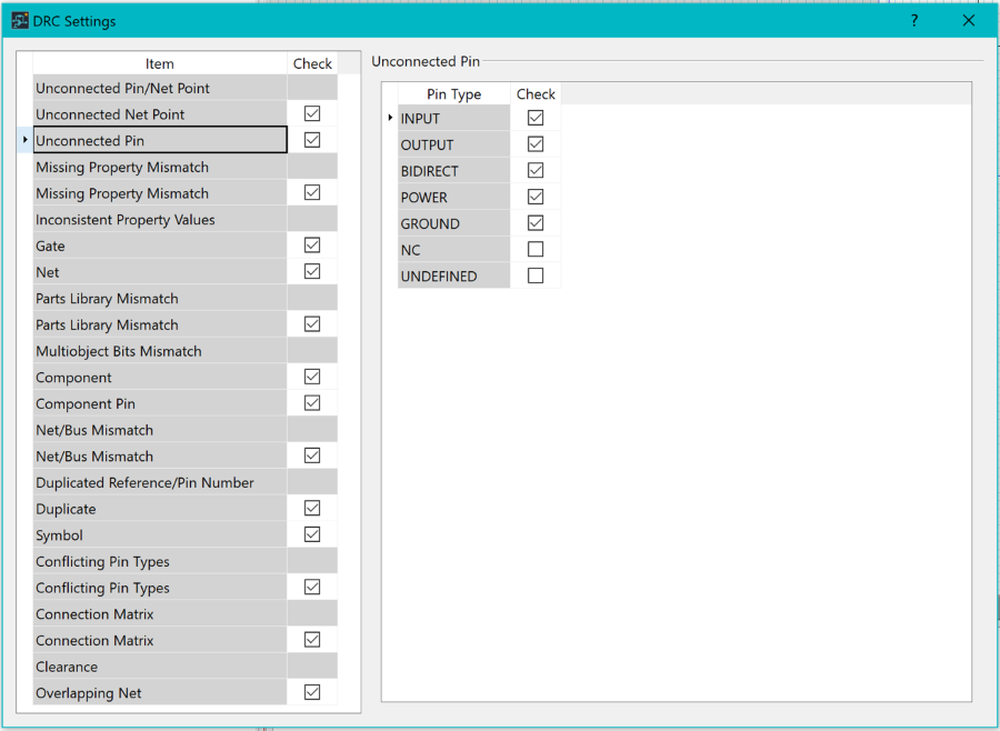
Figure 1: DRC Settings Dialog
DRC can be performed by clicking Report > Design Rule Checking > DRC on the ribbon. Select either Check Circuit or Check current sheet, and then click Execute.
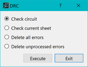
Figure 2: DRC Dialog
Parts Lists
You can configure parts lists to contain attribute values, as well as standard part information. A basic parts list is shown below.
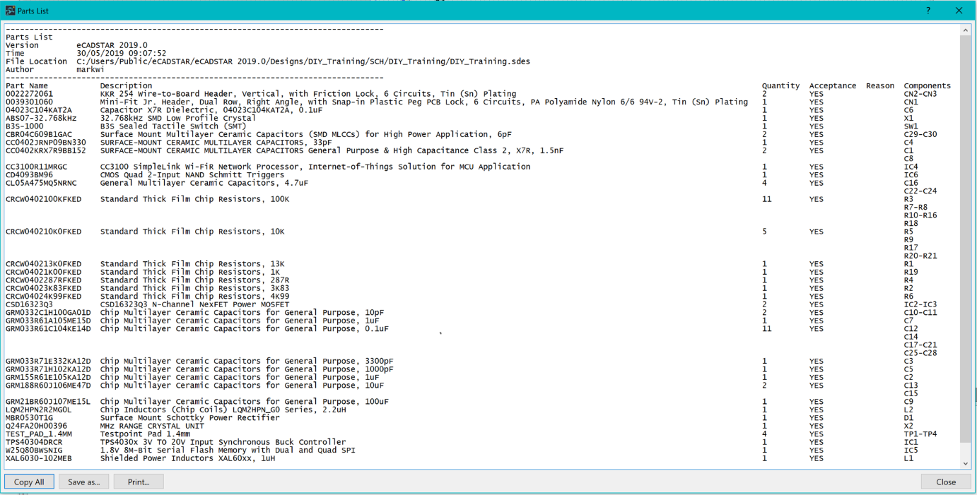
Figure 3: A Basic Parts List
Parts lists are produced by clicking Report > Part Output > Parts List Report on the ribbon. You can specify the contents of the report by clicking Report > Part Output > Parts List Report split button > Parts List Settings.
You can create customized reports using the PCB Report Generator command. Launch this command by clicking Report > User > Report Generator in eCADSTAR PCB Editor, or Report > User > PCB Report Generator in eCADSTAR Schematic Editor. This is illustrated below for eCADSTAR PCB Editor.
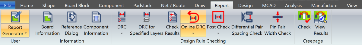
Figure 4: PCB Editor ribbon highlighting Report Generator
You have completed the eCADSTAR Schematic Editor training guide.
