
Task 2: Creating a New Schematic
In this section, you will learn how to create a new schematic design, and specify settings. You will also add components from the library, and make connections.
Task 2: Creating a New Schematic
Your choice of library is a product-level setting, so it applies to all eCADSTAR applications.
- From the Windows Start menu, launch eCADSTAR Schematic Editor.
- On the eCADSTAR Schematic Editor ribbon, select File > New. The New dialog is displayed.
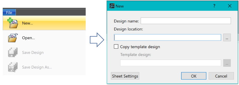
Figure 1: Creating a New Schematic Design
- In the Design Name box, specify "My_DIY_Training".
- In the Design Location box, specify “C:\Users\Public\eCADSTAR\eCADSTAR [version]\Designs\DIY_Training\SCH”.
- Click Sheet Settings. The Sheet Settings dialog is displayed.
- Click the Size/Zone tab, as shown below. The default settings are suitable for this training. Your schematic sheets will be A2 size, with items on the canvas snapped to a 1.0mm grid.
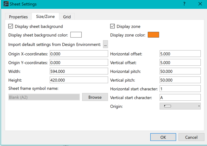
Figure 2: Sheet Settings
- Optionally, review the settings on each tab in the Sheet Settings dialog.
- In the Sheet Settings dialog, click Cancel.
- In the New dialog, click OK. You have created your first schematic sheet, and are now ready to add some components.
This task is demonstrated in the following video.
