
Task 3: Adding Parts and Symbols
The following procedure describes how to add parts and symbols to the schematic design that you created in the previous task.
- On the eCADSTAR Schematic Editor ribbon, select Home > Add > Part. The Part dialog is displayed. When you add a part, the schematic symbol is associated with a physical part in the library.
- In the Part dialog, select the "..." button by the Part Name box. The Library Searcher panel is displayed.
- In the Library Searcher panel, double-click part name CC3100R11MRGC to add this part symbol to the cursor. You can search more efficiently by typing the start of the name into the Part Name dialog, in the Library Searcher panel. For example, “CC31”.
As you point the cursor at a part name in the Library Searcher panel, a preview of the associated symbol and footprint is displayed.
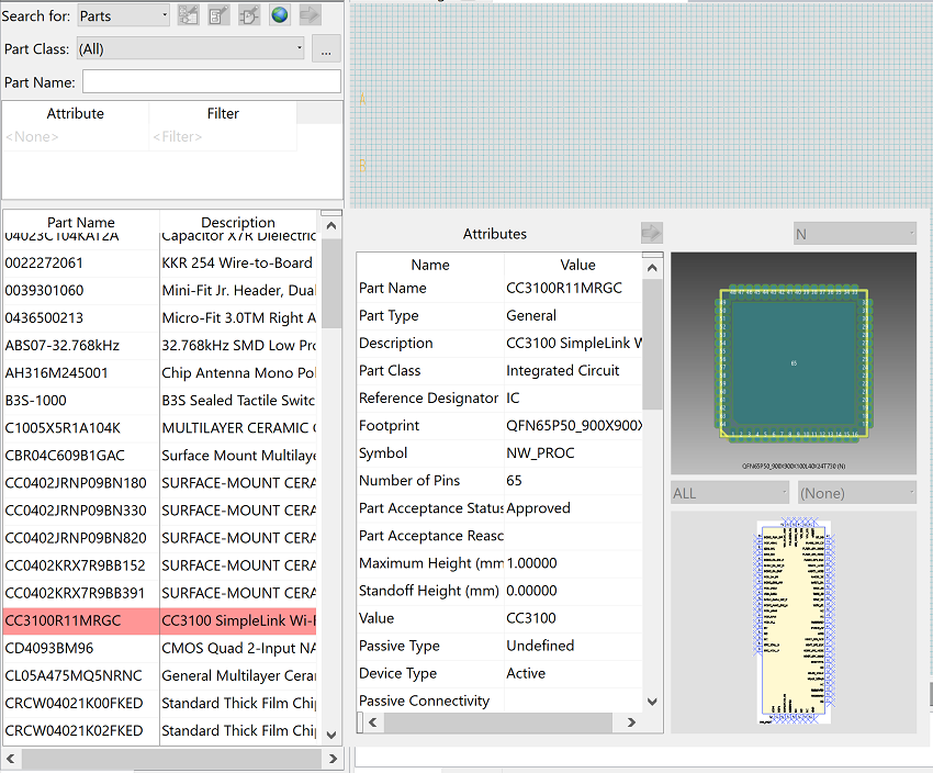
Figure 1: Selecting a Part in the Library Searcher Panel
- Click near the middle of the canvas to drop the part symbol onto the schematic sheet.
- Press Escon the keyboard to finish placing the symbol.
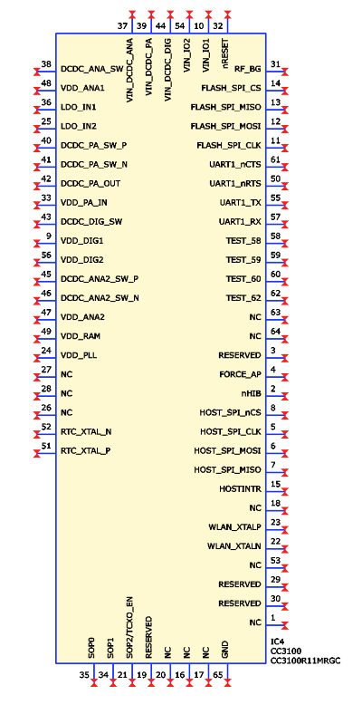
Figure 2: The Added Part Symbol
- Click the schematic symbol that you added to select it.
- On the eCADSTAR Schematic Editor ribbon, select View > Display > Properties. The Properties panel is displayed. Fields that have a white background allow you to add or edit values.
- For the part that you added, specify “IC4” in the Reference Designator box.
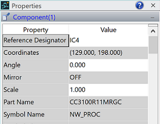
Figure 3: The Properties Panel
Alternatively, you could have specified the value for Reference Designator in the Part dialog.
-
Using the procedure described above, add the following parts in the positions shown in figure 4. When you select the resistor, specify "90" in the Part dialog, Rotation step box, and then right-click on the canvas and select Rotate by Specified Angle on the assist menu before you place the part.
- W25Q80BWSNIG, with reference designator “IC5”
- CRCW0402100KFKED, with reference designators “R14”, “R15” and “R16”
- GRM033R61C104KE14D, with reference designator “C28”
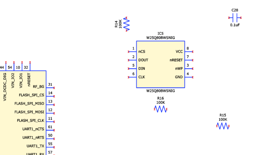
Figure 4: Part Layout
- On the eCADSTAR Schematic Editor
ribbon, click Component > Add > GND
split button, and select Ground (2)
in the list of available symbols. The Symbol
dialog is displayed, and the selected symbol is attached to the cursor.
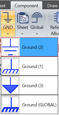
Figure 5: Ground Symbols - Place two Ground (2) symbols as shown in the image below.
- On the eCADSTAR Schematic Editor ribbon, click Component > Add > PWR split button and select Power+ve (1) in the list of available symbols. The Symbol dialog is displayed, and the selected symbol is attached to the cursor.
- Place two Power+ve (1) symbols as shown in the image below.
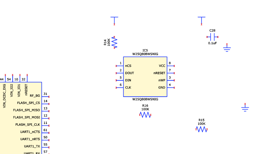
Figure 6: Part and Symbol Layout
This task is demonstrated in the following video.
