
Task 4: Adding and Naming Nets
Adding Nets
The following procedure describes how to add nets to a schematic design.
- On the eCADSTAR Schematic Editor ribbon, click Home > Add > Net. The Net dialog is displayed.
- In the Net dialog specify “FLASH_SPI_MISO” in the Net Label box.
- In the Wiring Mode box, select Auto Wiring.
- On IC4, click pin 13.
- On IC5, click pin 2, the net is added, as shown below.
- Press Escape on the keyboard, the Net dialog is closed.
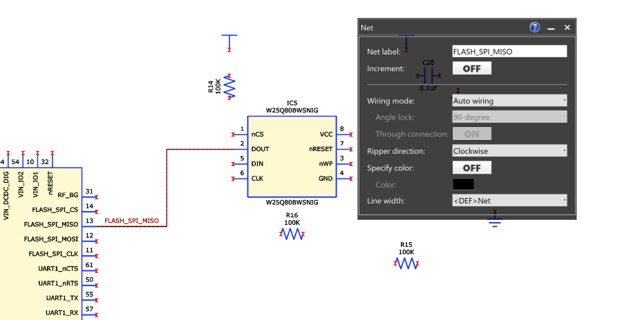
Figure 1: Adding a Net
You can adjust the net connection by selecting lines and dragging.
- Add more nets (not including VCC and GND), as shown in Figure 2, below. Do not name the nets. Optionally, experiment by selecting Manual Wiring and Semi-auto Wiring in the Wiring Mode box.
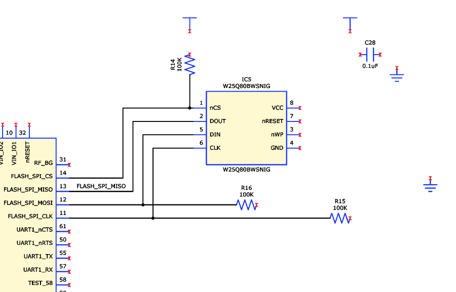
Figure 2: Signal Nets Added
This procedure is demonstrated in the following video.
Naming Nets
The following procedure describes how to name the nets that you added.
- On the eCADSTAR Schematic Editor ribbon, click Home > Label > Net/Bus. The Net/Bus dialog is displayed.
- On the canvas, select the highlighted unnamed net shown as “FLASH_SPI_MOSI” in Figure 2, above. Suggested names for the net are shown in the Net/Bus dialog; these suggestions are the pin labels of pins on the net.
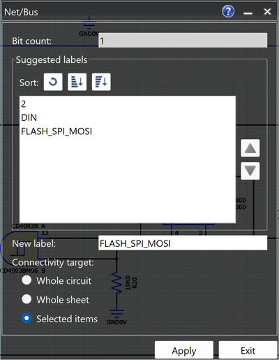
Figure 3: Pin Labels in the Net Name Dialog
- In the Net/Bus dialog, select FLASH_SPI_MOSI and click Apply.
- Select the net from IC4 pin 11, select the name FLASH_SPI_CLK in the dialog and click Apply.
- Select the net from IC4 pin 14, in the box for New Label. Change the name to FLASH_CSn and click Apply.
- On the eCADSTAR Schematic Editor ribbon, click File > Configuration > Application Settings. The Application Settings dialog is displayed.
- In the Application Settings dialog, click Advanced.
- In the Synchronization section, select Port Net Label, as shown below. Net labels that are currently empty are set to the names on the voltage symbols, when you add a net.
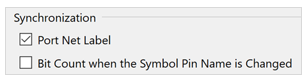
Figure 4: Synchronization Settings
- Click OK to apply the changes made in the Application Settings dialog.
This procedure is demonstrated in the following video.
Adding Power Nets
- On the eCADSTAR Schematic Editor ribbon, click Home > Add > Net. The Net dialog is displayed.
- In the Net dialog, starting in each case at the voltage symbol, enter the net names of the power nets VCC and GND0V into the Net Label box. The result should look similar to Figure 5, below. Do not make connections to capacitor C28.
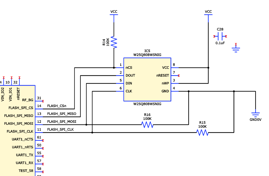
Figure 5: Synchronized Net Labels
You can adjust the display of the global symbol signal name by selecting the object, then in the Properties panel RMB click the Part Name cell and select Display Viewer. The signal name can then be positioned to a suitable location.
-
In the Net dialog, set Wiring Mode to Manual Wiring and Through Connection to ON, as shown below.
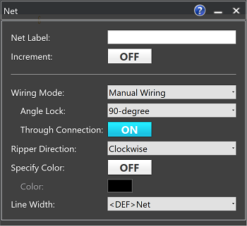
Figure 6: Enabling Through Connection
- Starting with a click at the ground symbol pin, click and add a corner at the horizontal axis of the capacitor.
- Move left over the existing connection, and attach to the existing VCC connection.
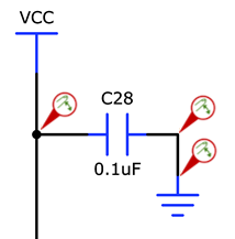
Figure 7: Detail of using the Through Mode
This procedure is demonstrated in the following video.
